High-precision indoor positioning method based on MEMS (Micro Electro Mechanical System) inertial sensor

An inertial sensor and indoor positioning technology, which is applied in the direction of instruments, navigation through speed/acceleration measurement, and measuring devices, can solve the problems of inability to initially align and low gyroscope accuracy, and achieve good positioning accuracy, small size, and strong popularity sexual effect

Inactive Publication Date: 2017-06-30
SOUTHEAST UNIV
View PDF6 Cites 44 Cited by
  • Summary
  • Abstract
  • Description
  • Claims
  • Application Information

AI Technical Summary

Problems solved by technology

Judging from the current research status of indoor positioning, MEMS indoor positioning has become a major research hotspot in foreign countries. Through the information output by MEMS inertial sensors, first judge the motion state of the carrier, and then perform zero-speed interval detection, and then perform zero-speed correction ( ZeroVelocity Update), which can well suppress the accumulation of MEMS inertial sensor errors. At the same time, the low-cost MEMS IMU gyroscope has low precision and cannot perform initial alignment according to the high-precision inertial navigation system initial alignment method. Because the magnetometer More stable than gyro Therefore, magnetometer is introduced to assist heading alignment and provide heading compensation
[0004] In the process of

Method used


Image

  • High-precision indoor positioning method based on MEMS (Micro Electro Mechanical System) inertial sensor
  • High-precision indoor positioning method based on MEMS (Micro Electro Mechanical System) inertial sensor
  • High-precision indoor positioning method based on MEMS (Micro Electro Mechanical System) inertial sensor

Examples


Embodiment Construction

[0045] The technical solution of the present invention will be further described in detail below in conjunction with the embodiments and the accompanying drawings.

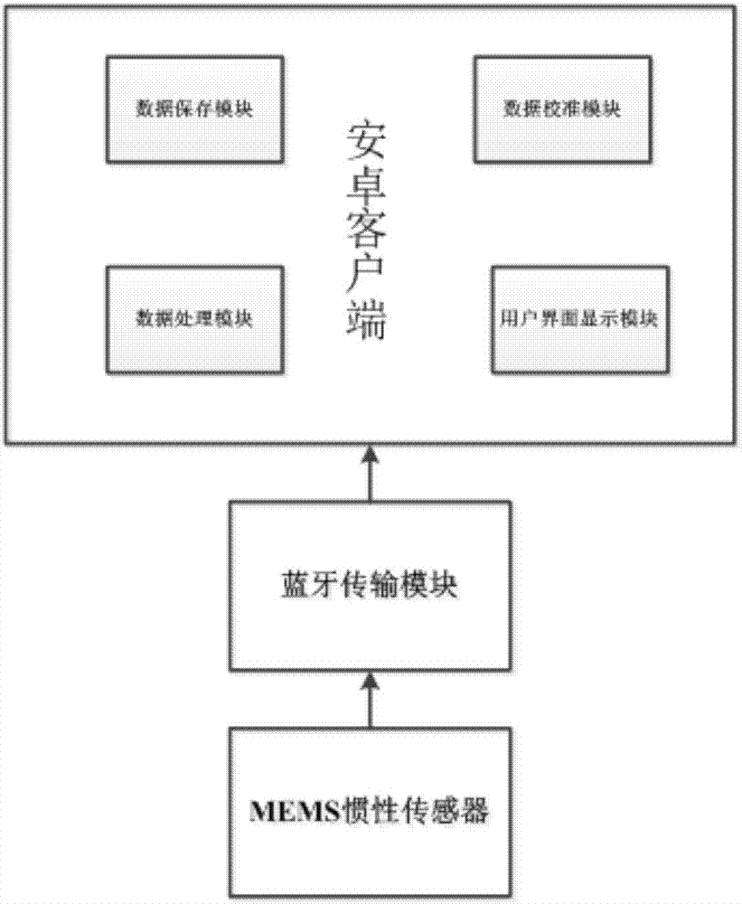
[0046] Such as figure 1 As shown, the high-precision indoor positioning equipment adopted in the present invention includes: low-cost MEMS inertial sensors such as MPU9260, MPU6050, etc., Bluetooth transmission module, android client; wherein, the android client includes a data calibration module, a data storage module, and a data processing module and a user interface display module. The MEMS inertial sensor is firmly connected to the foot, sensitive to the change of the footstep state, and transmits the measured parameters through the Bluetooth transmission module, and receives the data transmitted by the Bluetooth transmission module through the Android client. The Android client first calibrates the three-axis accelerometer, three-axis gyroscope, and three-axis magnetometer through the data calibration module...


PUM


Abstract

The invention discloses a high-precision positioning method based on an MEMS (Micro Electro Mechanical System) inertial sensor. The high-precision positioning method comprises the following steps: firstly, fixedly connecting the MEMS inertial sensor on a foot of a pedestrian, enabling the MEMS inertial sensor to sense a motion state of the foot, acquiring foot navigation information of the foot in real time, and realizing transmission by Bluetooth; secondly, holding an Android mobile phone by the pedestrian, and receiving and saving data provided by the MEMS inertial sensor in real time at an Android client; thirdly, carrying out denoising processing on the data; fourthly, obtaining a zero velocity interval by adopting a zero velocity detection algorithm, and then carrying out error correction by combining a zero velocity update algorithm with a state estimation algorithm; fifthly, displaying data subjected to error correction and compensation in real time by the Android client through a user interface. According to the high-precision positioning method disclosed by the invention, extra auxiliary basic setting is not needed; good positioning precision of various complex motion states in indoor positioning can be maintained; real-time correction and error compensation are realized by adopting a mobile terminal, and the motion track is displayed in real time by a user interaction interface.

Description

technical field [0001] The invention relates to an indoor positioning method, in particular to a MEMS inertial sensor-based high-precision indoor positioning method without installing additional infrastructure. Background technique [0002] Due to the development of the Internet and the popularity of mobile devices and personal devices, LBS (Location Based Services) has become more and more important. Users obtain location information and use it for navigation, tracking, monitoring, information push and other services. GPS can conveniently provide outdoor personal positioning information, but because GPS needs to receive at least 4 satellites to achieve positioning, its positioning effect is greatly affected by the received satellite signals, and in indoor environments, satellite signals cannot be received due to occlusion , seriously affecting its positioning effect. [0003] The inertial navigation system has the advantages of strong autonomy, high output frequency, and h...

Claims


Application Information

Patent Timeline
IPC IPC(8): G01C21/16G01C21/20
CPCG01C21/16G01C21/206
Inventor 张涛杨书天朱永云陈浩颜亚雄
Owner SOUTHEAST UNIV
Why Eureka
Try Eureka