Radar coincidence imaging method with array gain-phase errors

An array element amplitude and phase error, microwave correlation technology, applied in radio wave measurement systems, radio wave reflection/re-radiation, utilization of re-radiation, etc. Effect

An array element amplitude and phase error, microwave correlation technology, applied in radio wave measurement systems, radio wave reflection/re-radiation, utilization of re-radiation, etc. Effect

CN106918810AActive Publication Date: 2017-07-04NAT UNIV OF DEFENSE TECH

Image

  • Radar coincidence imaging method with array gain-phase errors
  • Radar coincidence imaging method with array gain-phase errors
  • Radar coincidence imaging method with array gain-phase errors

Examples


Embodiment Construction

[0039] The microwave correlation imaging method in the present invention when there is an array element amplitude and phase error will be described in detail below in conjunction with the accompanying drawings.

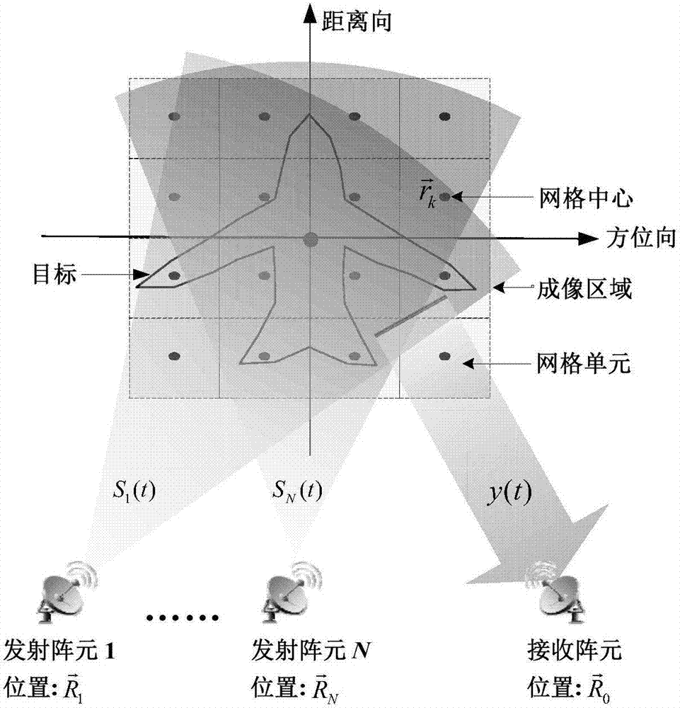
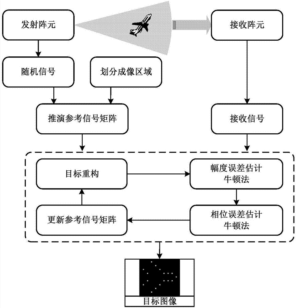
[0040] figure 1 It is a schematic diagram of the imaging geometry of the microwave correlation imaging radar described in the present invention. The radar array in the figure includes N transmitting array elements and 1 receiving array element, and the transmitting array elements transmit a set of mutually independent signals S n (t), n=1,2,...,N,S n(t) is a random signal that is independently distributed in the time domain. The transmitting signal of each transmitting array element forms a two-dimensional random radiation field randomly distributed in time and space in the imaging area, and the random radiation field modulated by the target is received by the receiving array element to obtain the echo y(t). When imaging, the imaging area is divided into several gr...


PUM


Abstract

The invention provides a radar coincidence imaging method with array gain-phase errors. The technical solution includes the following steps: a first step of receiving a radar echo, a radar coincidence imaging system being configured to include N transmitting arrays and one receiving array, the transmitting arrays transmitting a group of independent transmitting signals at the same time; a second step of dividing grids, evenly dividing an imaging region into grids with a size decided by imaging resolution; a third step of deducing a radiation field, using the iterative method to compute a radiation field reference signal; a fourth step of constructing an object, computing an object scattering coefficient vector based on the result of the iterative computing; a fifth step of estimating gain-phase errors; and a sixth step of using the object scattering coefficient vector to performing imaging if the result of the iterative computing meets requirements. According to the invention, the method can conduct high precision imaging on an object in the presence of gain-phase errors.

Description

technical field [0001] The invention relates to the technical field of microwave imaging, in particular to a microwave correlation imaging method, and more specifically relates to improving the quality of microwave correlation imaging when there is an array element amplitude and phase error. Background technique [0002] Microwave correlation imaging (Dongze Li, Xiang Li, Yuliang Qin, Yongqiang Cheng, and Hongqiang Wang, "Radar Coincidence Imaging: An Instantaneous Imaging Technique With Stochastic Signals," IEEE Transactions on Geoscience and Remote Sensing, vol.52, no.4, Apr. 2014) as a new staring imaging method, which does not depend on the relative motion between the radar and the target, has the advantages of high resolution, anti-interception, anti-jamming, etc. It has broad application prospects in the application fields such as earth observation. Microwave correlation imaging draws on the principle of classic optical correlation imaging to simulate the distribution...

Claims


Application Information

Patent Timeline
04 Jul 2017
Publication
CN106918810A
IPC
G01S13/89; G01S7/292
CPC
G01S7/292; G01S13/89
Inventors
秦玉亮; 程永强