
Eureka
For R&D, Eureka makes reading and utilizing patents & technical documents easy.
Eureka AIR
Designed for self-driven R&D workflows. Generate viable solutions, solve complex R&D challenges, empower your innovation with AI.

Eureka Materials
Designed for material experts only. Revolutionize your material R&D, from search, analyze, to developing new materials.

TechResearch
Generate reliable direction feasibility study reports for your R&D in just a few steps.

TechSeek
Discover and master advanced knowledge NOW. Basics, ideas, possibilities, all at once.

TechMind
As an expert in R&D Theories, TechMind can generates customized viable solutions instantly.

TechRisk
Analyze your overall solution with one click, know your potential R&D risks in advance.

TechMonitor
Get weekly tech updates, stay abreast of the latest tech innovations and key insights.
Split type high-speed motor
A high-speed motor, split-type technology, applied in the direction of electrical components, electromechanical devices, electric components, etc., can solve the problems of high-speed motor power increase, achieve the effect of increasing power, overcoming heat generation defects, and reliable operation
- Summary
- Abstract
- Description
- Claims
- Application Information
AI Technical Summary
Problems solved by technology
Method used
Image

Examples
Embodiment 1
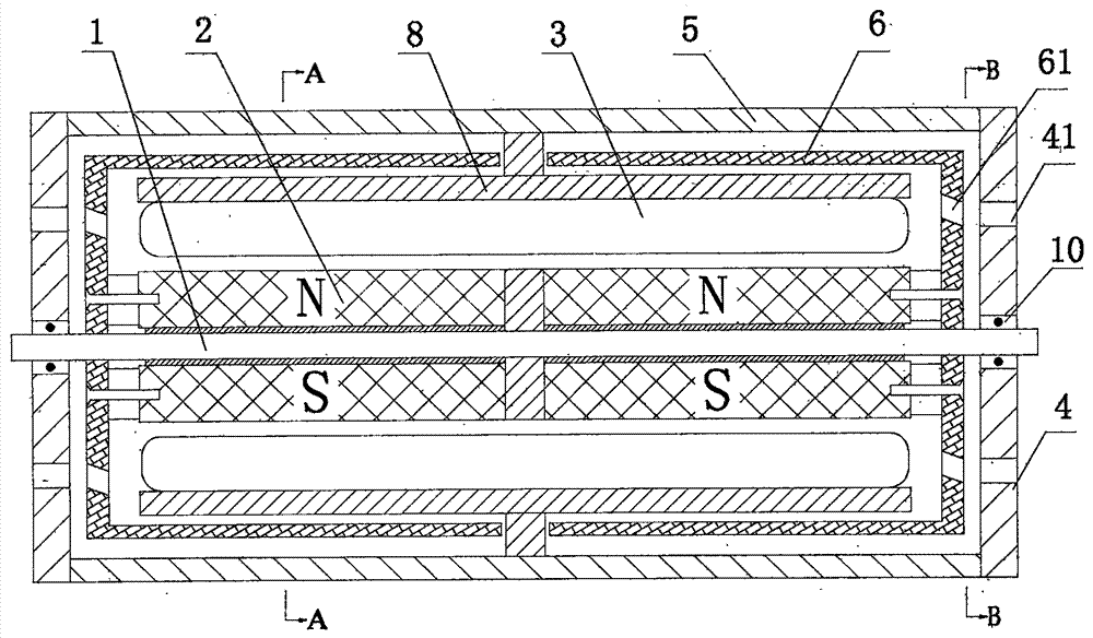
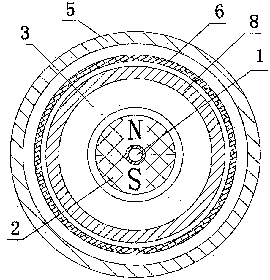
[0033] as attached figure 1 , 2 As shown, the stator coil and the permanent magnet rotor adopt a cylindrical structure.
[0034] Split type high-speed motor, including shaft 1, permanent magnet rotor 2, stator coil 3, bearing 10 and housing 5, stator coil 3 is fixed to the housing through bracket 8, permanent magnet rotor is fixed to the shaft, and the stator coil adopts ironless coil And it is a concentrated winding, and it can also be a hollow cup winding. In the housing, the rotor is divided into two parts, each part is composed of a permanent magnet rotor and an outer magnetic cylinder. The two parts of the rotor are symmetrically distributed in the cross section of the middle of the shaft; the two outer The openings of the magnetic tubes are arranged facing each other and placed in the middle of the motor. The bottom surfaces of the two outer magnetic tubes are respectively placed at the two end covers 4 close to the casing; the two outer magnetic tubes form a cavity; th...
Embodiment 2
[0039] Such as Figure 5 As shown, on the basis of Embodiment 1, the positions of the stator coil and the permanent magnet rotor are exchanged, the stator coil is on the inside and close to the shaft, the permanent magnet rotor is relatively outside and away from the shaft, and the stator coil is surrounded by the permanent magnet rotor;
[0040] Between the stator coil 3 and the shaft 1 there is also an inner magnetic tube 9, the inner magnetic tube, the permanent magnet rotor and the outer magnetic tube are fixed on the shaft through the connection part, and the three rotate together with the shaft. In this structure, the inner magnetically permeable cylinder can also adopt common magnetically permeable materials.
[0041] The stator coil 3 is located in the gap between the permanent magnet rotor 2 and the inner magnetically permeable ring cylinder 9 .
[0042] Other structures are the same or similar to the embodiment.
Embodiment 3
[0044] Such as Figure 6 As shown, the difference from Example 1 is that the direction of the two outer magnetic tubes is reversed, that is, the bottom surfaces of the two outer magnetic tubes face away from the middle of the motor, and the openings of the two outer magnetic tubes are respectively placed on the two end covers near the case.
[0045] The stator coil is also divided into two parts, and the two parts of the stator coil are also symmetrically distributed according to the radial cross-section of the middle part of the shaft. The end edges of the two parts of the stator coil are fixedly connected to the end cover through the bracket.
[0046] In the inner side of the end cover, the end of the cylindrical permanent magnet rotor is also provided with a conductive disk body 7, and the conductive disk body is fixed with the end cover 4 and can also be fixed with the shaft.
[0047] Other structures are the same or similar to Embodiment 1.
PUM
 Abstract
Description
Claims
Application Information
 - R&D Engineer
- R&D Manager
- IP Professional
- Industry Leading Data Capabilities
- Powerful AI technology
- Patent DNA Extraction
Browse by: Latest US Patents, China's latest patents, Technical Efficacy Thesaurus, Application Domain, Technology Topic, Popular Technical Reports.
© 2024 PatSnap. All rights reserved.Legal|Privacy policy|Modern Slavery Act Transparency Statement|Sitemap|About US| Contact US: help@patsnap.com