Tapered centrifugal beneficiation equipment

A mineral processing equipment and shrinkage technology, which is applied in the field of tapered flow film centrifugal mineral processing equipment and tapered centrifugal mineral processing equipment, can solve the problems of poor separation effect, low mineral processing capacity, and low enrichment ratio, etc., to achieve The separation effect is remarkable, the sorting time is shortened, and the application range is improved

Active Publication Date: 2017-07-07
KUNMING UNIV OF SCI & TECH
View PDF6 Cites 6 Cited by
  • Summary
  • Abstract
  • Description
  • Claims
  • Application Information

AI Technical Summary

Problems solved by technology

[0008]The present invention provides a kind of convenient operation, environmental protection, high efficiency, energy saving, can work independently and continuously and realizes the sorting independently and continuously under the working condition of non-stop. Discharge the fine tailings, which solves the problems of difficult separation and separation of fine-grained useful minerals, low enrichment ratio, and low beneficiation capacity caused by intermittent operation of beneficiation equipment in the existing flow film beneficiation technology; it can be processed with high efficiency and low consumption Low-grade, fine-grained raw ore and its old tailings, and refractory ore problems, effectively recycle the fine-grained valuable metals that cannot be recycled at present and are discharged into the tailings, so as to solve the common processing problems of existing equipment When dealing with fine-grained ores, the processing volume is small, the sorting effect is not good, and the cost is high, so as to realize the sustainable development of resources

Method used


Image

  • Tapered centrifugal beneficiation equipment
  • Tapered centrifugal beneficiation equipment
  • Tapered centrifugal beneficiation equipment

Examples


Embodiment 1

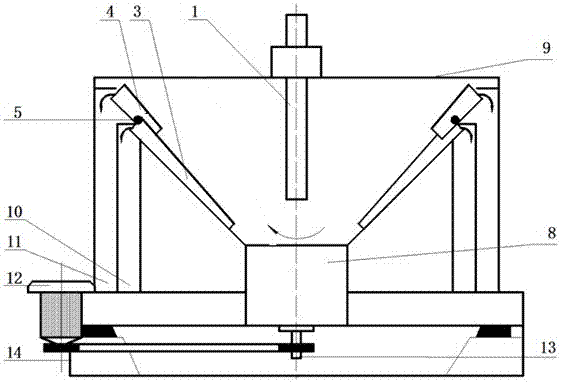
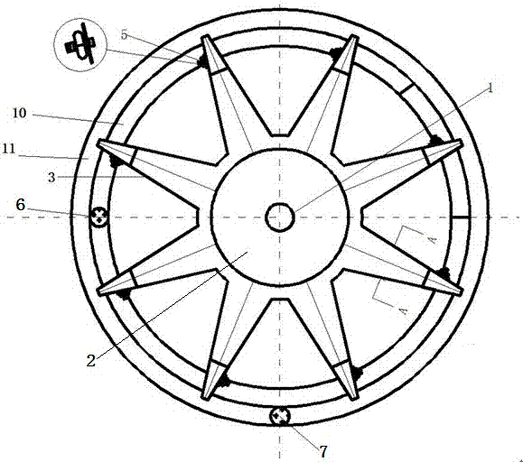
[0035] A kind of sharp-shrinking centrifugal beneficiation equipment, such as figure 1 , 2 , 3, and 4, including central ore feeding pipe 1, centrifugal drum 2, diverter tank 3, interceptor tank 4, hollow shaft rotating platform 8, shell 9, concentrate tank 10, tailings tank 11, drive motor 12, Hollow shaft 13, frame 14; centrifugal drum 2, interception tank 4, hollow shaft rotating platform 8, concentrate tank 10, tailings tank 11 are set inside the shell 9, centrifugal drum 2 and hollow shaft rotating platform 8 are located in the shell 9 center, the center of the bottom of the centrifugal drum 2 is connected with a hollow shaft rotating platform 8, and the central ore feeding pipe 1 passes through the shell 9 from the outside and faces the bottom of the centrifugal drum 2, so that minerals can be fed from the upper end of the central feeding pipe 1. into the bottom of the centrifugal drum 2, eight shunt grooves 3 are evenly arranged around the side wall of the centrifugal ...


PUM


Abstract

The invention discloses tapered centrifugal beneficiation equipment. The tapered centrifugal beneficiation equipment comprises a central ore feeding pipe, a centrifugal rotating drum, shunting grooves, intercepting grooves, a hollow shaft rotating platform, a shell, a concentrate groove, a tailing groove, a driving motor, a hollow shaft and a machine frame, wherein the centrifugal rotating drum, the intercepting grooves, the hollow shaft rotating platform, the concentrate groove and the tailing groove are arranged in the shell, the centrifugal rotating drum is located in the center of the interior of the shell, the central ore feeding pipe penetrates through the shell from outside to be right opposite to the bottom of the centrifugal rotating drum, the shunting grooves are uniformly formed in the periphery of the centrifugal rotating drum, the intercepting grooves are formed in the tail ends of the shunting grooves, the concentrate groove is formed in the outlets of the shunting grooves, the tailing groove is formed in the outlets of the intercepting grooves, the centrifugal rotating drum is arranged on the hollow shaft rotating platform, the hollow shaft rotating platform is connected with the hollow shaft, the hollow shaft is connected with the driving motor, and the driving motor is arranged on the machine frame. The tapered centrifugal beneficiation equipment is environment-friendly, efficient, energy-saving, capable of automatically and continuously discharging concentrate and tailings, high in efficiency, low in cost and suitable for high-efficiency sorting of fine-grain mineral so that the sustainable development of resources can be realized.

Description

technical field [0001] The present invention relates to a kind of constriction type centrifugal mineral processing equipment, in particular to a kind of constriction type flow film type centrifugal mineral processing which can continuously sort fine-grained valuable minerals, self-discharge ore, and recover efficiently and environmentally friendly under the action of a compound force field. The equipment belongs to the technical field of mineral processing. Background technique [0002] The ever-accelerating process of industrialization has forced the scale and intensity of mining resources to show a trend of continuous growth. Mineral resources are becoming increasingly depleted, and the resource crisis has become a global problem. [0003] Traditional slime beneficiation equipment mainly includes flow film and jigging gravity separation equipment such as cross-flow belt chute, shaking bed, slime shaker, spiral classifier and jig, and these two types only work under the act...

Claims


Application Information

Patent Timeline
Patent Type & Authority Applications(China)
IPC IPC(8): B04B1/00B04B7/00B04B11/02
CPCB04B1/00B04B7/00B04B11/02
Inventor 杨波孙欢肖日鹏
Owner KUNMING UNIV OF SCI & TECH
Why Eureka
Try Eureka