High-efficiency metal 3D printing equipment and method

A 3D printing and metal technology, applied in the field of 3D printing, can solve problems such as slow running speed, difficult control of process parameters, and high production costs

Active Publication Date: 2017-07-07
UNIV OF SCI & TECH BEIJING
View PDF6 Cites 25 Cited by
  • Summary
  • Abstract
  • Description
  • Claims
  • Application Information

AI Technical Summary

Problems solved by technology

[0007] The present invention aims at the existing metal 3D printing technology that adopts direct feeding of melt and cooling by cooling medium, which has high production cost, poor equipment mechanism action flexibility, slow running speed, low printing efficiency, difficult control of process parameters and forming Due to poor product quality and repeatability, it is proposed to separate the feeding system and discharging system of the equipment, separate the printing and forming area from the cooling medium, place the feeding system outside the forming chamber, and adjust the size of the outlet of the nozzle according to the size of the product. On this basis, a new type of metal 3D printing technology will be developed

Method used


Image

  • High-efficiency metal 3D printing equipment and method

Examples


Embodiment 1

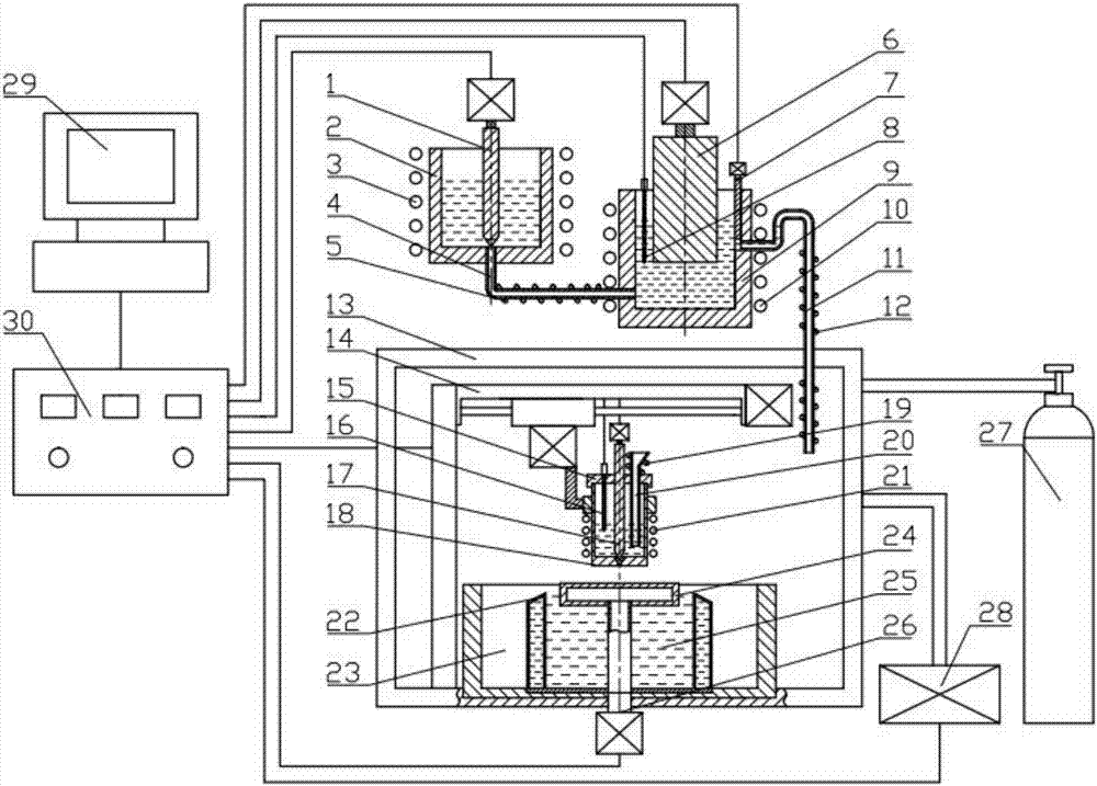
[0051] Efficient 3D printing of pure tin cans.

[0052] According to the size and precision requirements of pure tin cans, the diameter of the outlet of the nozzle 18 is selected to be 1.5mm; the nozzle top cover 15 is installed above the nozzle 18, the sealing door of the forming chamber 13 is closed, and the sealing baffle 7 is controlled by the controller 30 Block the liquid outlet of the holding furnace 9, open the vacuum system 28, and vacuumize the forming chamber 13; close the vacuum system 28, open the inflation system 27, and fill the forming chamber 13 with protective gas until the forming chamber 13 The air pressure reaches an atmospheric pressure; the liquid outlet at the bottom of the melting furnace 2 is blocked by controlling the melting furnace stopper rod 1 through the controller 30, and solid pure tin raw materials are loaded into the melting furnace 2; the melting furnace heater 3 is turned on, and the melting furnace 2 The pure tin raw material is heated to...

Embodiment 2

[0054] Efficient 3D printing of tin alloy parts.

[0055]According to the size and precision requirements of the tin alloy parts, the diameter of the nozzle 18 discharge opening is selected to be 1mm; the nozzle top cover 15 is installed on the nozzle 18, the sealing door of the forming chamber 13 is closed, and the sealing baffle 7 is controlled by the controller 30 The liquid outlet of the holding furnace 9 is blocked, open the vacuum system 28, and vacuumize the forming chamber 13; close the vacuum system 28, open the inflation system 27, and fill the forming chamber 13 with protective gas until the air pressure in the forming chamber Reach an atmospheric pressure; Control the melting furnace plug rod 1 by the controller 30 to block the liquid outlet at the bottom of the melting furnace 2, and load the solid tin alloy raw material into the melting furnace 2; Tin alloy raw material is heated to 350 DEG C; Turn on melt transmission pipeline heater 5, holding furnace heater 10...

Embodiment 3

[0057] Efficient 3D printing of copper alloy molds.

[0058] According to the size and precision requirements of the copper alloy mould, the diameter of the nozzle 18 discharge port is selected to be 2 mm; the nozzle top cover 15 is installed on the top of the nozzle 18, the sealing door of the forming chamber 13 is closed, and the sealing baffle 7 is controlled by the controller 30. The liquid outlet of the holding furnace 9 is blocked, open the vacuum system 28, and vacuumize the forming chamber 13; close the vacuum system 28, open the inflation system 27, and fill the forming chamber 13 with protective gas until the air pressure in the forming chamber Reach an atmospheric pressure; Control the melting furnace plug rod 1 by the controller 30 to block the liquid outlet at the bottom of the melting furnace 2, and load solid copper alloy raw materials into the melting furnace 2; Heat the copper alloy raw material to 1250°C; turn on the melt transfer pipe heater 5, the holding f...


PUM


Abstract

The invention discloses high-efficiency metal 3D printing equipment and a method, and belongs to the technical field of 3D printing. Through such measures as separation of a supply system of metal 3D printing equipment from a discharge system, separation of a printing forming area from a cooling medium, positioning of the supply system out of a forming room and capability of controlling the size of a discharge port of a nozzle according to sizes of products, based on direct melt supply and cooling medium cooling, the high-efficiency metal 3D printing equipment and method adopt 3D printing to form high-quality metal products with high efficiency and low cost, and in particular, are suitable for high-efficiency formation of large metal products. The 3D printing equipment is flexible in mechanism actions, fast in operating speed, high in flexibility, high in sensitivity and low in manufacturing cost; the 3D printing forming process is high in efficiency; process parameters are liable to control; and the metal products formed by printing are excellent in quality and repeatability and low in production cost.

Description

technical field [0001] The invention belongs to the technical field of 3D printing, and in particular relates to a high-efficiency metal 3D printing device and method. [0002] technical background [0003] 3D printing technology is a new type of material forming technology developed in the early 1980s. Its principle is to first use a computer to establish a three-dimensional solid model of the product to be formed, and then use layered slicing software to process the three-dimensional solid model of the product into a A series of two-dimensional cross-sections, and then use 3D printing equipment to accumulate materials layer by layer according to the shape of two-dimensional cross-sections, and finally form a three-dimensional solid product. 3D printing technology has the characteristics of short production process and high material utilization rate, and can realize near-net shape production of complex shapes, small batches and personalized products. [0004] Since its ince...

Claims


Application Information

Patent Timeline
Patent Type & Authority Applications(China)
IPC IPC(8): B22F3/105B33Y30/00B33Y10/00
CPCB33Y10/00B33Y30/00B22F10/00B22F12/10B22F10/73B22F10/22B22F12/57B22F12/90B22F10/32B22F12/20B22F12/53Y02P10/25
Inventor 刘雪峰李昂俞波尹宝强颜阳
Owner UNIV OF SCI & TECH BEIJING
Why Eureka
Try Eureka