Low-noise vibration excitation support
A low-noise, vibration-exciting technology, applied in the direction of ceramic molding machines, manufacturing tools, etc., can solve problems such as mold, workbench vibration exciter damage, damage to workers' hearing, flatness is not easy to guarantee, etc., to eliminate internal voids, The effect of improving plant utilization and reducing adverse effects
- Summary
- Abstract
- Description
- Claims
- Application Information
AI Technical Summary
Problems solved by technology
Method used
Image
Examples
Embodiment 1
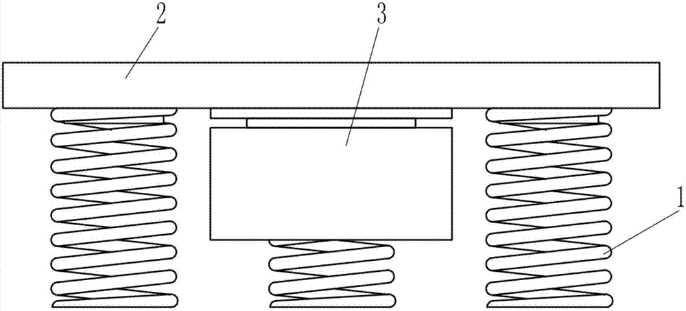
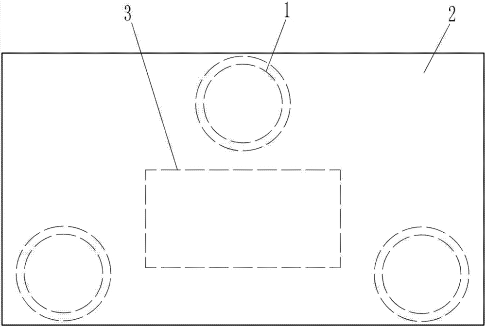
[0025] Such as figure 1 with figure 2 The low-noise excitation support of the present invention shown includes three elastic elements 1, a coupling base 2 and a vibration exciter 3. The vibration exciter 3 is tightly fixed on the middle of the lower surface of the coupling base 2, and the elastic element 1 is located on the coupling base 2 below and elastically supports the coupling base 2, and the elastic element 1 is arranged around the exciter 3. Among them, the elastic element 1 is specifically a spiral steel spring.
[0026] In application, an appropriate number of low-noise excitation supports of the present invention are selected according to the weight of the concrete component to be processed and the size of the mold, such as image 3 with Figure 4 As shown, the mold 4 is supported by six low-noise excitation supports of the present invention. The low-noise excitation supports are placed on a flat and solid foundation surface 5. When concrete is poured into the mold 4, ...
Embodiment 2
[0030] Such as Figure 5 with Image 6 The difference between the low-noise excitation support of the present invention and the first embodiment is that four elastic elements 1 are provided. Among them, the first-order natural frequency of the vibration system formed by the elastic element and the mass of the weight supported during operation is equal to the excitation One-half of the minimum working excitation frequency of the device 3; in addition, a quick positioning structure is fixedly arranged on the connecting base 2, and the quick positioning structure is specifically a guide plate 6 fixedly arranged on the connecting base 2 and a part of the connecting base The modal frequency of the first-order structure is equal to 1.15 times the maximum operating frequency of the exciter 3.
[0031] When applied, such as Figure 7 As shown, the mold 4 is supported by four low-noise excitation supports of the present invention, and the guide plates 6 in the low-noise excitation supports...
Embodiment 3
[0034] Such as Figure 8 The difference between the low-noise excitation support of the present invention and the second embodiment is that a quick positioning structure is fixedly arranged on the coupling base 2. The quick positioning structure is specifically a positioning pin 7; in addition, the low-noise excitation support It also includes a support foot 8, the support foot 8 is arranged in a one-to-one correspondence with the elastic element 1, and the elastic element 1 is placed on the support foot 8.
[0035] Compared with the second embodiment, the technical solution described in this example is provided with a positioning pin 7 on the coupling base 2 and a corresponding positioning hole is provided on the mold, so that the low-noise excitation support of the present invention can be well implemented in application. For quick assembly between molds, of course, the quick positioning structure can also be an integrated convex-concave structure on the connecting base. Only th...
PUM
| Property | Measurement | Unit |
|---|---|---|
| strength | aaaaa | aaaaa |
Abstract
Description
Claims
Application Information
 - R&D
- Intellectual Property
- Life Sciences
- Materials
- Tech Scout
- Unparalleled Data Quality
- Higher Quality Content
- 60% Fewer Hallucinations
Browse by: Latest US Patents, China's latest patents, Technical Efficacy Thesaurus, Application Domain, Technology Topic, Popular Technical Reports.
© 2025 PatSnap. All rights reserved.Legal|Privacy policy|Modern Slavery Act Transparency Statement|Sitemap|About US| Contact US: help@patsnap.com


