Power supply control device, vehicle, and power supply control method
一种电源控制装置、车辆的技术,应用在控制装置、电池/燃料电池控制装置、用电装置等方向,能够解决无法充分减小高电压系统电压变动、电压偏离容许范围等问题
- Summary
- Abstract
- Description
- Claims
- Application Information
AI Technical Summary
Problems solved by technology
Method used
Image

Examples
no. 1 approach
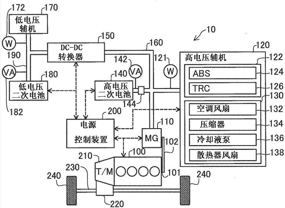
[0026] figure 1 It is an explanatory diagram showing the vehicle 10 of the first embodiment. The vehicle 10 includes an engine 100, a generator 110, a high-voltage auxiliary machine 120, a high-voltage secondary battery 140, a battery sensor 142, a relay 144, a DC-DC converter 150, a high-voltage wiring 160, a low-voltage auxiliary machine 170, a low-voltage Voltage secondary battery 180 , low voltage wiring 190 , power control device 200 , transmission 210 , power splitter 220 , drive shaft 230 , and drive wheels 240 .
[0027]In the first embodiment, an internal combustion engine is used as the engine 100 . The generator 110 is a generator connected to the rotating shaft 101 of the engine 100 via a power transmission mechanism 102 such as a belt or gears, and generates electricity by the rotation of the engine 100 . The high-voltage auxiliary machine 120 is an auxiliary machine connected to the high-voltage line 160 and operated at a relatively high voltage. The high-volt...
no. 2 approach
[0052] Figure 5 is a control flowchart of the second embodiment. The action of step S135, S155, S165 and figure 2 The flow chart of the first embodiment shown is different, and the operation of other steps is the same as that of the first embodiment. In step S165, the power control device 200 except figure 2 In addition to the processing of step S160, the control target value of the voltage on the low-voltage wiring 190 side of the DC-DC converter 150 is set to a predetermined value Vpb. This control target value Vpb is set, for example, to a value equal to the open-circuit voltage of the low-voltage secondary battery 180 . In step S135, the power source control device 200 sets the control target value of the voltage on the low-voltage wiring 190 side of the DC-DC converter 150 to a value larger than Vpb (Vpb+Vdc1) in addition to the processing of step S130. ). Here, Vdc1 is determined such that Vpb+Vdc1 is equal to or less than the upper limit of the allowable voltage...
no. 3 approach
[0056] Image 6 is a control flowchart of the third embodiment. In addition, the control processing of the third embodiment can be compared with that of the first embodiment figure 2 The control process of the second embodiment or the Figure 5 The control processing is executed in parallel. In steps S200 and S205 , as in steps S100 and S105 of the first embodiment, when the high-voltage secondary battery 140 fails, the power supply control device 200 is shut off by the relay 155 . In step S206, the power supply control device 200 acquires the first auxiliary machine 122 among the high-voltage auxiliary machines 120 ( figure 1 ) power consumption Ph1. In addition, in the third embodiment, it is preferable to provide two power meters, a first power meter for measuring the power consumption of the first auxiliary machine 122 and a second power meter for measuring the power consumption of the second auxiliary machine 130, as Power meter 121 for high voltage auxiliary machin...
PUM
 Abstract
Description
Claims
Application Information
 - R&D
- Intellectual Property
- Life Sciences
- Materials
- Tech Scout
- Unparalleled Data Quality
- Higher Quality Content
- 60% Fewer Hallucinations
Browse by: Latest US Patents, China's latest patents, Technical Efficacy Thesaurus, Application Domain, Technology Topic, Popular Technical Reports.
© 2025 PatSnap. All rights reserved.Legal|Privacy policy|Modern Slavery Act Transparency Statement|Sitemap|About US| Contact US: help@patsnap.com