High-voltage electromagnetic valve state detection device and high-voltage electromagnetic valve state detection method

A state detection device, high-voltage solenoid valve technology, applied in the direction of measuring devices, circuit breaker testing, measuring electricity, etc., can solve the problems that pressure fluctuations cannot be maintained, the main steam isolation valve is closed, and the oil pump is frequently started, etc., to ensure pressure, The effect of ensuring authenticity, improving exhaust efficiency and stabilizing effect

Active Publication Date: 2017-07-07
RES INST OF NUCLEAR POWER OPERATION +1
View PDF5 Cites 6 Cited by
  • Summary
  • Abstract
  • Description
  • Claims
  • Application Information

AI Technical Summary

Problems solved by technology

[0002] When the high-voltage solenoid valve in the power plant is used, faults such as action time out-of-tolerance, leakage, refusal to operate, and malfunction may occur, which may cause the normal operation of related systems in the nuclear power plant and even cause certain accidents.
For example, the leakage of the solenoid valve on the main steam isolation valve of the pressurized water reactor nuclear power plant will cause pressure fluctuations that cannot be maintained, frequent start-up of the oil pump, and even lead to the closure of the main steam isolation valve, seriously affecting the safe operation of the unit
At present, most nuclear power plants use routine inspection, component replacement or overall replacement to carry out preventive maintenance. Corrective maintenance is carried out after obvious faults are found. Little is known about the status and performance of solenoid valves, and there are mis-repairs, missed repairs, and over-repairs. Phenomena such as these have caused major safety hazards to nuclear power plants

Method used


Image

  • High-voltage electromagnetic valve state detection device and high-voltage electromagnetic valve state detection method

Examples


Embodiment Construction

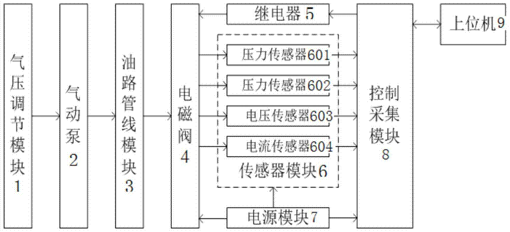
[0018] A high-pressure solenoid valve state detection device

[0019] Including the air pressure adjustment module 1, the air pressure adjustment module 1 is connected with the pneumatic pump 2, the air pressure adjustment module 1 provides the working air source for the air pump 2, and the pressure of the air source can be adjusted; the air pressure pump 2 is connected with the oil pipeline module 3, and the air pump 2 Provide oil pressure for the oil pipeline module 3; the oil pipeline module 3 is connected to the solenoid valve 4, the solenoid valve 4 includes an inlet and a discharge port, and the oil pipeline module 3 provides specified oil pressure for the inlet and discharge port of the solenoid valve 4; the solenoid valve 4 is the test object, which is connected with the relay 5, the sensor module 6, and the power module 7 respectively, wherein the power module 7 provides power for the solenoid valve 4, the sensor module 6, and the control acquisition module 8 respectiv...


PUM


Abstract

The invention discloses a high-voltage electromagnetic valve state detection device and a high-voltage electromagnetic valve state detection method. The high-voltage electromagnetic valve state detection device comprises an air pressure regulation module, a pneumatic pump, an oil pipeline module, an electromagnetic valve, a relay, a sensor module, a power module, a control and acquisition module, and an upper computer, wherein the air pressure regulation module is connected with the pneumatic pump; the air pressure regulation module provides a working air source for the pneumatic pump, and the pressure of the air source can be regulated; the pneumatic pump is connected with the oil pipeline module; the pneumatic pump provides oil pressure for the oil pipeline module; the oil pipeline module is connected with the electromagnetic valve; the electromagnetic valve comprises an inlet and an outlet, and the oil pipeline module provides specified oil pressure for the inlet and the outlet of the electromagnetic valve; and the electromagnetic valve is a tested object and is connected with the relay, the sensor module and the power module respectively, and the power module provides power for the electromagnetic valve, the sensor module and the control and acquisition module.

Description

technical field [0001] The invention belongs to the field of detection devices, and in particular relates to a high-voltage electromagnetic valve state detection device and method. Background technique [0002] Power plant high-voltage solenoid valves may have faults such as out-of-tolerance action time, leakage, refusal to operate, and malfunctions during use, which may cause normal operation of related systems in nuclear power plants and even cause certain accidents. For example, leakage of the solenoid valve on the main steam isolation valve of a pressurized water reactor nuclear power plant will cause pressure fluctuations that cannot be maintained, frequent start-up of the oil pump, and even cause the main steam isolation valve to close, seriously affecting the safe operation of the unit. At present, most nuclear power plants use routine inspection, component replacement or overall replacement to carry out preventive maintenance. Corrective maintenance is carried out af...

Claims


Application Information

Patent Timeline
Patent Type & Authority Applications(China)
IPC IPC(8): G01R31/327
CPCG01R31/3271Y02P90/02
Inventor 舒芝锋黄萍朱翠云杨津瑞李剑宋猛
Owner RES INST OF NUCLEAR POWER OPERATION
Why Eureka
Try Eureka