Positioning installation structure of ellipsoidal reflector

A technology of positioning installation and mirror, applied in the direction of installation, photoplate making process of pattern surface, exposure device of photoplate making process, etc. small impact effect

Active Publication Date: 2017-07-07
SHANGHAI MICRO ELECTRONICS EQUIP (GRP) CO LTD
View PDF7 Cites 6 Cited by
  • Summary
  • Abstract
  • Description
  • Claims
  • Application Information

AI Technical Summary

Problems solved by technology

[0004] In the prior art, the positioning installation structure for fixing the ellipsoidal reflector is as follows: figure 1 and figure 2 As shown, the ellipsoidal reflector 5 has a round hole 04 on the bottom surface, and the ellipsoidal reflector 5 is placed on the positioning bracket 01, and the contact position between the positioning bracket 01 and the ellipsoidal reflector 5 has a dispensing point 02, and the ellipsoidal reflector 5 The glue point 02 is bonded with the positioning bracket 01, and the positioning bracket 01 is fixedly installed in the lithography machine system through the installation positioning hole 03 and the screw placed in the installation positioning hole 03. Since the ellipsoidal mirror 5 is in the During the working process, it needs to be irradiated by the lighting source, so its own temperature will inevitably rise, resulting in thermal deformation. Because of this positioning installation structure and installation method, the ellipsoidal reflector 5 is only connected to the positioning bracket 01 by bonding , once the temperature rises, the glue melts, and the ellipsoidal mirror 5 is deformed, the positioning accuracy will be greatly affected
[0005] Therefore, in view of the above problems, it is necessary to invent a positioning and installation structure for the ellipsoidal reflector, which can solve the problem that the installation accuracy of the ellipsoidal reflector is affected by thermal expansion and deformation during the working process

Method used


Image

  • Positioning installation structure of ellipsoidal reflector
  • Positioning installation structure of ellipsoidal reflector
  • Positioning installation structure of ellipsoidal reflector

Examples


Embodiment Construction

[0036] In order to make the above objects, features and advantages of the present invention more comprehensible, specific implementations of the present invention will be described in detail below in conjunction with the accompanying drawings.

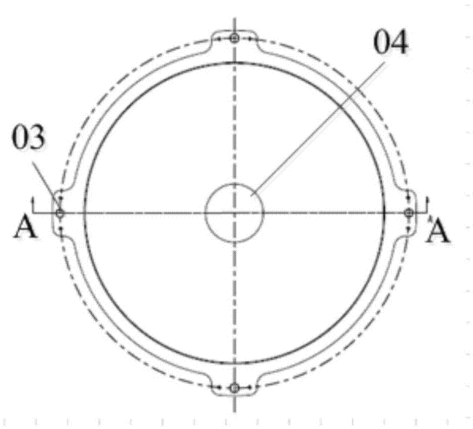
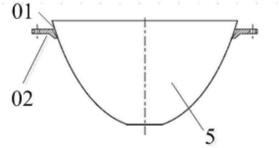
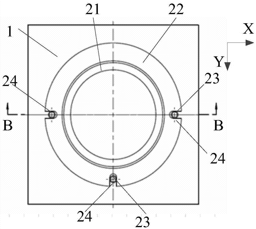
[0037] To achieve the above purpose, please refer to image 3 and Figure 4 , the present invention provides a positioning and installation structure for an ellipsoidal reflector, which is located at the bottom of the ellipsoidal reflector 5, and includes a support base plate 1 and a positioning seat 2 from bottom to top. The ring post boss 21 in the circular hole at the bottom of the ellipsoid reflector 5 and the positioning ring post 22 fixedly connected with the ring post boss 21, the ring post boss 21 and the positioning ring post 22 are integrated parts, the outer diameter of the positioning ring post 22 is greater than the outer diameter of the ring post boss 21, the axis of the ring post boss 21 coincides with the axis of the p...


PUM


Abstract

The invention provides a positioning installation structure of an ellipsoidal reflector. The structure comprises a positioning seat located at an ellipsoidal reflector bottom. The positioning seat comprises a circular ring column boss inserted into a circular hole of the ellipsoidal reflector bottom and a positioning circular ring column fixedly connected to the circular ring column boss from top to bottom. Therefore, an axis of the ellipsoidal reflector can be fixed; and even if the ellipsoidal reflector generates thermal expansion and is deformed, the axis is fixed so that an influence of thermal expansion deformation on positioning precision can be reduced.

Description

technical field [0001] The invention relates to the field of semiconductor photolithography machines, in particular to a positioning and installation structure of an ellipsoidal reflector. Background technique [0002] In the integrated circuit manufacturing process, a complete chip usually requires multiple photolithography exposures to complete. In photolithography, the object to be exposed (usually a wafer) is carried by the workpiece table. An optical measurement system is often placed above the workpiece table, and a mask is placed between the two. During photolithography, the optical measurement system passes through Observation and measurement, transmit data to the control system, and then the control system moves the workpiece table so that the mask plate is aligned with the predetermined area of ​​the wafer on the workpiece table, and the exposure starts after alignment. [0003] In the optical measurement system, the ellipsoidal reflector is an important part, and...

Claims


Application Information

Patent Timeline
Patent Type & Authority Applications(China)
IPC IPC(8): G02B7/182G03F7/20
CPCG02B7/182G03F7/2008
Inventor 许凯迪陈宇环
Owner SHANGHAI MICRO ELECTRONICS EQUIP (GRP) CO LTD
Why Eureka
Try Eureka