Numerical method for simulating rotor flow field of water turbine

A numerical method and technology of hydraulic turbines, which are applied in the fields of electrical digital data processing, special data processing applications, instruments, etc., can solve the problems of uncertainty in the stability of convergence, and cannot be further improved.

Inactive Publication Date: 2017-07-07
成都金景盛风科技有限公司
View PDF0 Cites 2 Cited by
  • Summary
  • Abstract
  • Description
  • Claims
  • Application Information

AI Technical Summary

Problems solved by technology

[0009] 2. The spatial discrete precision of the added vorticity is limited and cannot be further improved;
[0010] 3. The

Method used


Image

  • Numerical method for simulating rotor flow field of water turbine
  • Numerical method for simulating rotor flow field of water turbine
  • Numerical method for simulating rotor flow field of water turbine

Examples


Embodiment Construction

[0067] The numerical simulation technology proposed by the present invention will be further described below with a specific embodiment. It can be implemented with Fortran90 high-level computer programming language, and simulate the flow of the flow field of the three-dimensional water turbine rotor through computer operation.

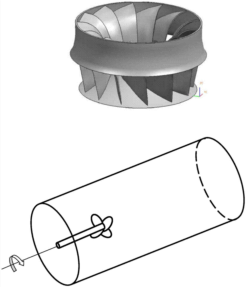
[0068] In the specific implementation, the shape and calculation domain of the turbine rotor are as follows image 3 shown. The turbine rotor with 16 blades has a surface diameter of 0.227m and a chord length of 0.086m at 70% of the disk surface radius. The computational domain adopts a rotating coordinate system, and the direction of rotation is shown by the middle arrow. The calculation grid adopts unstructured tetrahedral grid. The spatial discretization of the numerical simulation adopts the Finite Volume Method, and each calculation grid becomes a control unit, and the flow variable is at the center of the control unit.

[0069] The flight con...


PUM


Abstract

The invention discloses a numerical method for simulating a rotor flow field of a water turbine. According to characteristics of incompressible flow, force in two different forms is added in a momentum equation to improve numerical simulation precision of a type of flow field based on a vortex motion. The force in the two forms is spiral force and viscous dissipation force of vorticity in a varying gradient direction respectively.

Description

technical field [0001] The invention relates to a numerical method in the application field of computational fluid mechanics, in particular to a numerical method for simulating the rotor flow field of a water turbine. Background technique [0002] Among the hydraulic mechanical devices, the hydraulic turbine has become the most important hydroelectric power generation device in the world because of its relatively simple structure, high propulsion efficiency, and a long history of development and experimental experience. The rotor of a water turbine is composed of multiple blades, and the rotating blades generate thrust in the water, which is similar to the lift generated by aircraft wings. However, there is a big difference in the wake flow field between the turbine rotor and the aircraft wing. The wake flow field of the turbine rotor is called the flow field, which is a vortex-dominated incompressible flow field full of vortex flow. figure 1 Taking a blade as an example, ...

Claims


Application Information

Patent Timeline
IPC IPC(8): G06F19/00
CPCG16Z99/00
Inventor 路明
Owner 成都金景盛风科技有限公司
Why Eureka
Try Eureka