Vehicle workpiece non-rigid 3D point cloud registration method based on linear mixed deformation

A technology of 3D point cloud and linear mixing, which is applied in image data processing, instrumentation, computing, etc., and can solve the problem that the ICP method is no longer applicable

Active Publication Date: 2017-07-07
宁波智能装备研究院有限公司
View PDF3 Cites 4 Cited by
  • Summary
  • Abstract
  • Description
  • Claims
  • Application Information

AI Technical Summary

Problems solved by technology

[0003] The purpose of the present invention is to solve the problem that the existing ICP can only solve the problem of rigid body transformation. For the reference point cloud P after non-rigid body downsampling, when the downsampled reference point cloud P is deformed due to its own gravity or external force, the original The shortcomings of the ICP method are no longer applicable, and a non-rigid 3D point cloud registration method for automotive workpieces based on linear mixed deformation is proposed

Method used


Image

  • Vehicle workpiece non-rigid 3D point cloud registration method based on linear mixed deformation
  • Vehicle workpiece non-rigid 3D point cloud registration method based on linear mixed deformation
  • Vehicle workpiece non-rigid 3D point cloud registration method based on linear mixed deformation

Examples


specific Embodiment approach 1

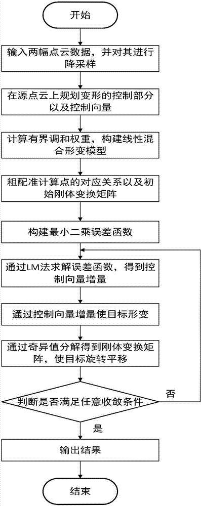
[0033] Specific implementation mode one: combine figure 1 To illustrate this embodiment, the specific process of a non-rigid 3D point cloud registration method for automobile workpieces based on linear hybrid deformation in this embodiment is as follows:

[0034] Step 1: Input the reference point cloud Q' and the source point cloud P' into the program, use the grid filter method to perform down-sampling, and obtain the down-sampled reference point cloud Q and source point cloud P;

[0035] Step 2: Plan the deformed point on the downsampled source point cloud P, that is, the control point, and construct the control vector S; artificially plan, select the point that will be deformed on the downsampled source point cloud P, which is the control point Points, according to the degrees of freedom that these control points may move (each point has three degrees of freedom x, y, z), plan the control vector (define all required variables as a vector, for example, each control point ha...

specific Embodiment approach 2

[0044] Specific embodiment two: the difference between this embodiment and specific embodiment one is: in the step three, the bounded harmonic weight set W is calculated, and the specific process is:

[0045] Minimize the equation:

[0046]

[0047] and satisfy the following constraints:

[0048]

[0049]

[0050]

[0051] where δ jk is the Kronecker function, when j=k, δ jk The value is 1, otherwise δ jk The value is 0; Δω j for ω j Increment; ω j as the control point The corresponding bounded harmonic weights; is the jth control point, j=1,2,...,m, m is the number of control points, and the value of m is a positive integer, is the kth control point, and the value of k is a positive integer, is the point on the source point cloud before deformation, is the jth control point at The weight at , j is the control point, i is the point on the source point cloud P, and the value of i is a positive integer. The control point is the point artificially plan...

specific Embodiment approach 3

[0053] Specific embodiment three: the difference between this embodiment and specific embodiment one or two is: in the step three, a linear mixed deformation model is constructed, and the specific formula is:

[0054]

[0055] in is the point on the deformed source point cloud, ψ j as the control point The rigid body transformation matrix of .

[0056] Other steps and parameters are the same as those in Embodiment 1 or Embodiment 2.


PUM


Abstract

The invention discloses a vehicle workpiece non-rigid 3D point cloud registration method based on linear mixed deformation. The invention relates to the vehicle workpiece non-rigid 3D point cloud registration method based on linear mixed deformation. The invention aims to solve a disadvantage that the an original ICP method is not applicable when a reference point cloud P is deformed due to gravity of the reference point cloud P or external force for the reference point cloud P which is subjected to non-rigid downsampling at present. The method comprises the steps of (1) obtaining Q and P, (2) constructing a control vector S, (3) constructing a linear mixed deformation model, (4) calculating an initial rigid transformation matrix, (5) constructing a least squares error function, (6) obtaining Delta S, (7) obtaining P', (8) allowing P' to rotate and translate, (9) obtaining the transformation relation between initial source point cloud and the reference point cloud, and (10) judging whether the obtained transformation relation between the initial source point cloud and the reference point cloud satisfies a convergence condition, outputting a result if so, otherwise going to the step (4). The method is used in the field of automobile workpiece registration.

Description

technical field [0001] The invention relates to a non-rigid body three-dimensional point cloud registration method of an automobile workpiece based on linear mixed deformation. Background technique [0002] With the development of RGB-D cameras, it is possible to obtain high-quality 3D point clouds of objects at low cost, and it also promotes the development and application of stereo vision. 3D point cloud registration is a very important problem in stereo vision. This technology has rich applications in reverse engineering, robot vision positioning, 3D measurement and other fields. The Iterative Closest Point (ICP, Iterative Closest Point) algorithm proposed by Besl et al. is a relatively mature and widely used algorithm in point cloud registration. However, ICP can only solve the problem of rigid body transformation. For the reference point cloud P after non-rigid body downsampling, when the downsampled reference point cloud P is deformed due to its own gravity or externa...

Claims


Application Information

Patent Timeline
Patent Type & Authority Applications(China)
IPC IPC(8): G06T7/33
Inventor 林伟阳叶超李湛于兴虎
Owner 宁波智能装备研究院有限公司
Why Eureka
Try Eureka