CMOS image sensor and formation method therefor
An image sensor and dielectric layer technology, applied in the direction of electric solid-state devices, semiconductor devices, electrical components, etc., can solve the problem of serious bright spots in CMOS image sensors, and achieve the effect of reducing leakage current, suppressing grain growth, and avoiding bright spots.
- Summary
- Abstract
- Description
- Claims
- Application Information
AI Technical Summary
Problems solved by technology
Method used
Image

Examples
Embodiment 1
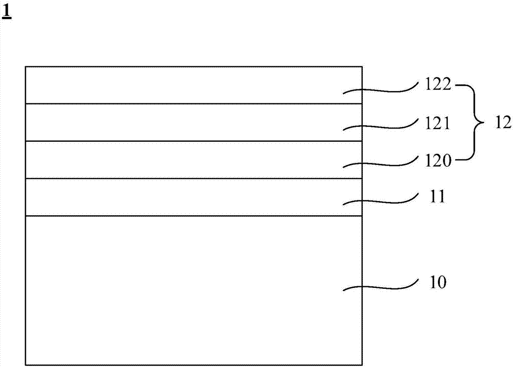
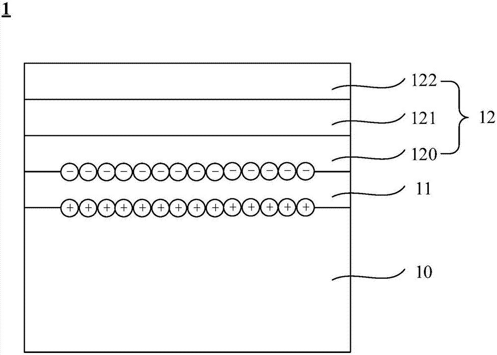
[0028] Please refer to figure 1 , which is a schematic structural diagram of a CMOS image sensor according to Embodiment 1 of the present invention. Such as figure 1 As shown, in the embodiment of the present application, the CMOS image sensor 1 includes: a semiconductor substrate 10, a first oxide layer 11 formed on the semiconductor substrate 10, and a first oxide layer 11 formed on the first oxide layer 11. The first high-K dielectric layer 12, wherein the first high-K dielectric layer 12 includes multiple first high-K dielectric sub-layers, and the interface between two adjacent first high-K dielectric sub-layers is discontinuous. Here, the first high-K dielectric layer 12 includes three first high-K dielectric sub-layers, which are respectively the first high-K dielectric sub-layer 120, the first high-K dielectric sub-layer 121 and the first high-K dielectric sub-layer 122.
[0029] Specifically, a semiconductor substrate 10 is provided first. Preferably, the semicond...
Embodiment 2
[0038] Please refer to Figure 4 , which is a schematic structural diagram of a CMOS image sensor according to Embodiment 2 of the present invention. Such as Figure 4 As shown, in the embodiment of the present application, the CMOS image sensor 2 includes: a semiconductor substrate 20, a first oxide layer 21 formed on the semiconductor substrate 20, and a first oxide layer 21 formed on the first oxide layer 21. The first high-K dielectric layer 22, the second high-K dielectric layer 23 formed on the first high-K dielectric layer 22, and the second oxide layer 24 formed on the second high-K dielectric layer 23, wherein, The first high-K dielectric layer 22 includes multiple first high-K dielectric sub-layers, and the interface between two adjacent first high-K dielectric sub-layers is discontinuous. Here, the first high-K dielectric layer 22 includes two first high-K dielectric sublayers, namely the first high-K dielectric sublayer 220 and the first high-K dielectric sublaye...
Embodiment 3
[0047] Please refer to Figure 5 , which is a schematic structural diagram of a CMOS image sensor according to Embodiment 3 of the present invention. Such as Figure 5 As shown, in the embodiment of the present application, the CMOS image sensor 3 includes: a semiconductor substrate 30, a first oxide layer 31 formed on the semiconductor substrate 30, and a first oxide layer 31 formed on the first oxide layer 31. The first high-K dielectric layer 32, the second high-K dielectric layer 33 formed on the first high-K dielectric layer 32, and the second oxide layer 34 formed on the second high-K dielectric layer 33; wherein, The first high-K dielectric layer 32 includes multiple first high-K dielectric sub-layers, and the interface between two adjacent first high-K dielectric sub-layers is discontinuous; the second high-K dielectric layer 33 includes multiple first high-K dielectric sub-layers. For the second high-K dielectric sublayer, the interface between two adjacent second h...
PUM
| Property | Measurement | Unit |
|---|---|---|
| Thickness | aaaaa | aaaaa |
| Thickness | aaaaa | aaaaa |
| Thickness | aaaaa | aaaaa |
Abstract
Description
Claims
Application Information
 - Generate Ideas
- Intellectual Property
- Life Sciences
- Materials
- Tech Scout
- Unparalleled Data Quality
- Higher Quality Content
- 60% Fewer Hallucinations
Browse by: Latest US Patents, China's latest patents, Technical Efficacy Thesaurus, Application Domain, Technology Topic, Popular Technical Reports.
© 2025 PatSnap. All rights reserved.Legal|Privacy policy|Modern Slavery Act Transparency Statement|Sitemap|About US| Contact US: help@patsnap.com