Tunneling effect of artificial surface plasmon and working method thereof
A plasmon, artificial surface technology, applied in the field of guided wave structure, can solve the problems of long-distance transmission and high loss of curved transmission, and achieve the effect of small size, wide application and convenient integration
- Summary
- Abstract
- Description
- Claims
- Application Information
AI Technical Summary
Problems solved by technology
Method used
Image

Examples
Embodiment 1
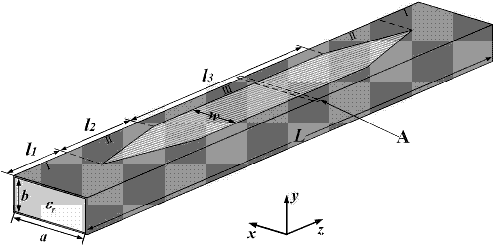
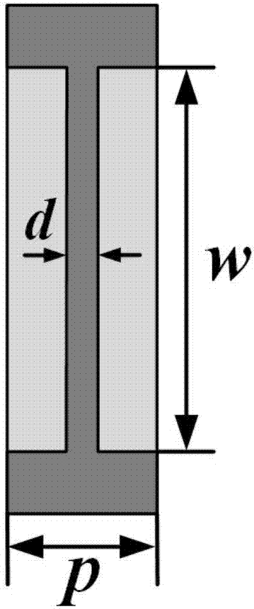
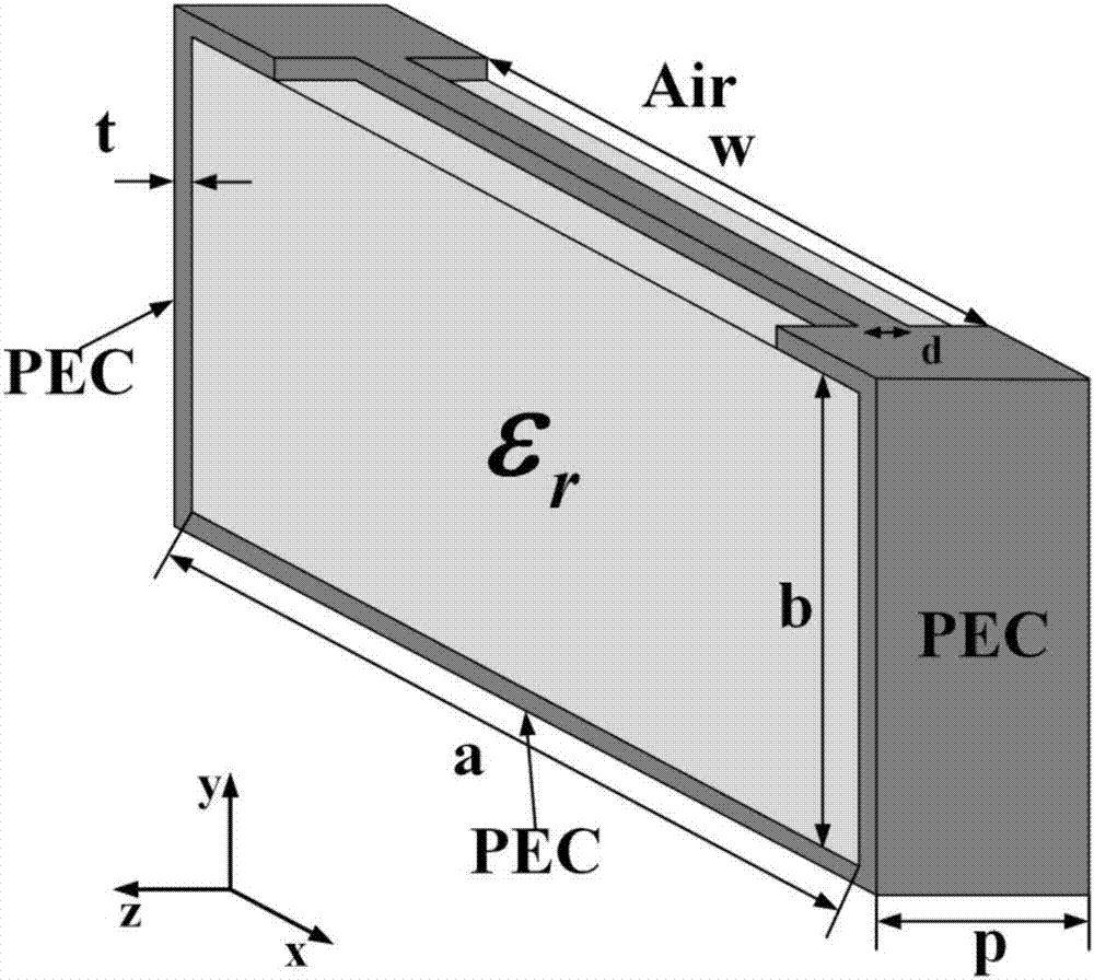
[0041] Analysis of pristine plasmonic waveguides supporting artificial surface plasmon tunneling, such as figure 1 , figure 2 , the port size is a*b=22.86*10.16mm 2 , which is mainly composed of three parts, namely, a rectangular waveguide at both ends (area I), a transitional waveguide (area II), and a plasmonic waveguide (area III). The length of the rectangular waveguide is l 1 = a, the transition waveguide length is l 2 = 2a, the length of the plasmonic waveguide is l 3 = 3a. The structural unit of the plasmonic waveguide is as image 3 , the metal upper wall of the rectangular waveguide is cut out and connected by a metal strip. Its geometric size is mainly determined by several parameters, namely the dimensions a and b of the cross section, the width w of the slit, the period p, and the length of the metal strip. width d. Such as Figure 4a , Figure 4b , Figure 4c , Figure 4d As shown, different parameters are changed to simulate the dispersion of the struct...
Embodiment 2
[0043] Such as Figure 6a-Figure 6c As shown, the tunneling channel filled with zero effective dielectric constant material is connected to the plasmonic waveguide, and the inverted U-shaped channel, H-shaped channel, and U-shaped channel are analyzed, corresponding to Model 1 (Model1) and Model 2 (Model2) , Model 3 (Model3), the length of the tunneling channel is l 4 =4a, width is w c = a / 4, here the medium filled in the plasmonic waveguide is ε r1 = 4, the relative permittivity of the filling in the tunneling channel is ε r2 =2.4, and metal strips are periodically arranged at the interface of the two media. According to the formula It can be calculated that the frequency point where the tunneling effect occurs is about 4.24GHz. Using electromagnetic simulation software, it can be obtained that Figure 7 The transmission coefficient (S 21 ) and reflection coefficient (S 11 ), curve 1-curve 3 in the figure correspond to model 1-model 3 respectively. There are two tra...
Embodiment 3
[0045] To further verify that the tunneling effect of artificial surface plasmons is not affected by the channel geometry, as Figure 8 As shown, keep the total length of the tunneling channel l 4 Consistent with Model 3, the inverted U-shaped tunneling channel in Example 2 is bent at 90 degrees. Here, the filling in the tunneling channel is still a medium with a relative permittivity of 2.4. The transmission coefficient curve and The reflection coefficient curve is as Figure 9 As shown, there are two transmission peaks, and the first transmission peak is still at 4.24GHz, which is consistent with the results of the first three models in Example 2, proving that artificial surface plasmons can perform bend tunneling .
[0046] A working method for the tunneling effect of artificial surface plasmons, comprising the following steps:
[0047] TE in a rectangular waveguide 10 The mode is converted into an artificial surface plasmon. Under the action of the tunneling channel, t...
PUM
 Abstract
Description
Claims
Application Information
 - R&D
- Intellectual Property
- Life Sciences
- Materials
- Tech Scout
- Unparalleled Data Quality
- Higher Quality Content
- 60% Fewer Hallucinations
Browse by: Latest US Patents, China's latest patents, Technical Efficacy Thesaurus, Application Domain, Technology Topic, Popular Technical Reports.
© 2025 PatSnap. All rights reserved.Legal|Privacy policy|Modern Slavery Act Transparency Statement|Sitemap|About US| Contact US: help@patsnap.com