Color temperature chip for detecting LED wall switch and circuit using same

A wall switch and chip technology, which is applied in the field of color temperature chips and circuits using color temperature chips, can solve the problems of color temperature chip burnout, limit the scope of application, and not be able to control multiple LED constant current drivers, so as to save application costs and make breakthroughs Application limitations, the effect of realizing multi-channel drive control

Active Publication Date: 2017-07-07
深圳砺芯半导体有限责任公司
View PDF4 Cites 1 Cited by
  • Summary
  • Abstract
  • Description
  • Claims
  • Application Information

AI Technical Summary

Problems solved by technology

[0008] Shortcomings of the prior art: A: Since the AC input is an AC signal, diode D1 is required for isolation, and the chip ports CLK, D1, and D2 cannot withstand high voltage, and the CLK port needs to be connected to a voltage dividing resistor; D1, D2 can only control constant current The power supply end of the driver chip, due to the withstand voltage of D1 and D2, limits the scope of application; if the voltage dividing resistor of the CLK port is soldered open circuit during the production process, the color temperature chip will be burned directly, causing the application system to be irreparable. Only the color temperature chip can be replaced, which is a waste of cost; B: There are only two output terminals of the color temperature chip, which cannot control multiple LED constant current drivers

Method used


Image

  • Color temperature chip for detecting LED wall switch and circuit using same
  • Color temperature chip for detecting LED wall switch and circuit using same
  • Color temperature chip for detecting LED wall switch and circuit using same

Examples


Embodiment 3

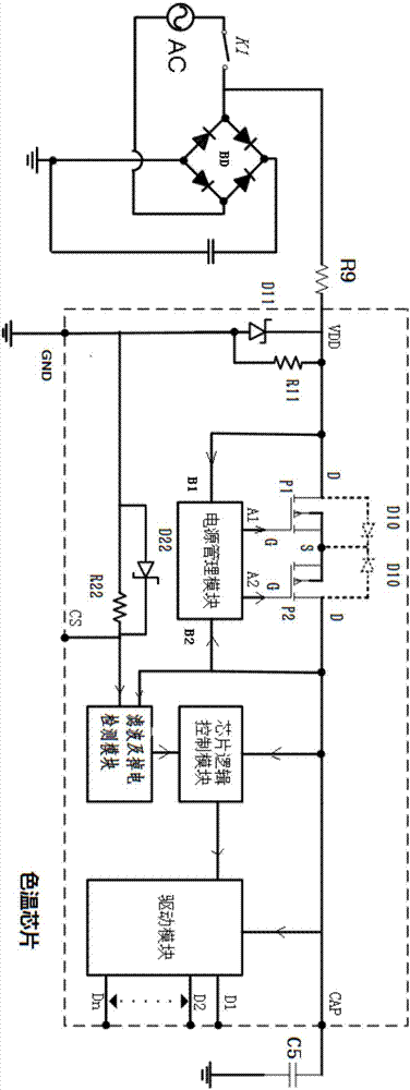
[0034] Embodiment 3 is an application to implement an isolation precursor circuit of the color temperature chip, such as Figure 4 , including a rectifier bridge stack, N constant current drive chips, N transformers and N LED lamp groups, the AC mains is connected to the AC input end of the rectifier bridge stack through a wall switch K1, and the DC output end of the rectification bridge stack is passed through N constant current drive chips and N transformers drive and connect N LED lamp groups (it is the prior art, and the connection structure and working principle will not be described in detail here), and also includes the color temperature chip described in Embodiment 1, the color temperature The VDD pin of the chip is connected to the on-off state point of the wall switch K1 through a resistor R1, the CS pin of the color temperature chip is short-circuited with the VDD pin, and the CAP pin of the color temperature chip is connected to the wall switch K1 through a capacito...

Embodiment 4

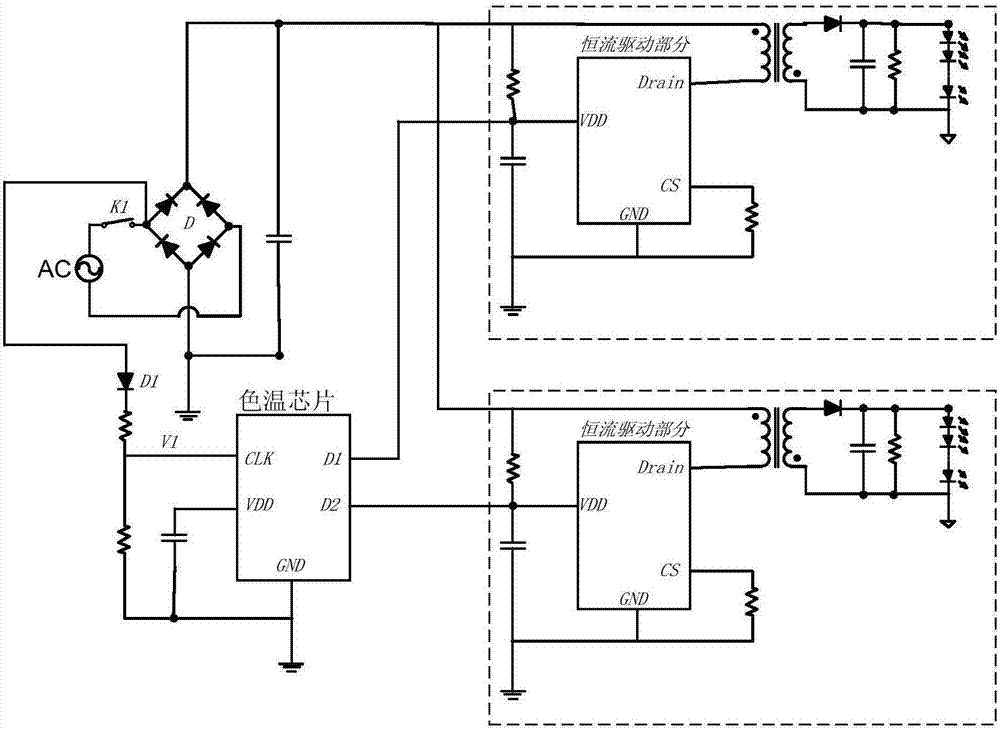
[0035] Embodiment 4 is an application to implement an isolation precursor circuit of the color temperature chip, such as Figure 5 The difference from the third embodiment is that the VDD pin of the color temperature chip is connected to the positive pole of the DC output terminal of the rectifier bridge stack through a resistor R, the CAP pin of the color temperature chip is short-circuited with the VDD pin, and the The CS pin of the color temperature chip is connected to the on-off state point of the wall switch K1 through a resistor R, the GND pin is grounded, and the N drive output pins D1, D2, D3, ... Dn of the color temperature chip are respectively connected to The VDD ends of N constant current drive chips, the Drain ends of the N constant current drive chips are connected to N transformers; this circuit is the same as the prior art ( figure 1 ), the isolation diode D1, the VDD voltage divider resistor and the CAP capacitor are omitted, and the prior art can only real...


PUM


Abstract

The invention provides a color temperature chip for detecting an LED wall switch. The chip comprises a power supply management module, a chip logic control module, a filter and power failure detection module and a drive module. The chip is provided with (N+4) groups of pins, and comprises a VDD pin, a CAP pin, a GND pin, a CS pin, and N drive output pins D1, D2, D3, ..., Dn. The VDD pin is connected with the CAP pin through a PMOS tube back-to-back structure inside the chip. N output ends of the drive module are connected with N drive output pins D1, D2, D3, ..., Dn of the chip. According to the invention, a resistor, a diode and a capacitor component outside the chip are reduced on the original application system, which saves the application cost of the system; the chip can be used for a variety of isolated or non-isolated different applications, which breaks the application limitation of the original scheme; groups of selectable ports are arranged on the drive output end of the chip; a variety of different drive tubes are packaged in the chip, and different voltage withstand values can meet the needs of a variety of different applications; and the chip can be in drive connection with N LED light strings (N is greater than 2) to realize multi-channel drive control.

Description

technical field [0001] The invention relates to the technical field of mobile phone structural parts, in particular to a color temperature chip for detecting an LED wall switch and a circuit using the color temperature chip. Background technique [0002] LED applications are divided into two categories: display and lighting. The new type of lighting that uses light-emitting diodes (LEDs) as the light source is called semiconductor lighting, or LED lighting for short, and the industry with semiconductor lighting as the main body is called the LED lighting industry. Under the double pull of domestic industrial policy and international market demand, China's LED lighting product market is developing rapidly. At present, global LED production capacity is shifting to China, and about 50% of the world's LED packaging and more than 60% of LED applications are carried out in China. my country has become the fastest growing region in the global semiconductor lighting industry. [...

Claims


Application Information

Patent Timeline
Patent Type & Authority Applications(China)
IPC IPC(8): H05B33/08H05B44/00
CPCH05B45/00
Inventor 朱小安陈伟邵宇
Owner 深圳砺芯半导体有限责任公司
Why Eureka
Try Eureka