
Linear partial motive sealing moving mechanism provided with X-ray protection function

A motion mechanism, linear motion technology, applied in the field of seal motion mechanism, linear partial dynamic seal motion mechanism, can solve the problems of increasing vacuum pump power, increasing space, increasing cost, etc., to reduce the amount of seal compression, reduce motion resistance, The effect of reducing the sealing resistance

Active Publication Date: 2017-07-11
桂林实创真空数控设备有限公司
View PDF19 Cites 1 Cited by
  • Summary
  • Abstract
  • Description
  • Claims
  • Application Information

AI Technical Summary

Problems solved by technology

[0004] 1. O-shaped rubber sealing ring and rectangular or dovetail groove sealing groove are usually used. This structure often makes the sealing ring come out during the installation process, and the installation is more difficult; because the sealing groove is a combination of long rectangle and arc in the horizontal direction structure, it is more difficult to process, and it is difficult to guarantee the accuracy and smoothness of the sealing surface
[0005] 2. In order to ensure the vacuum seal, the rubber ring needs to be pressed tightly, so that the resistance during movement is very large, and it can only be used to adjust the seam at a slow speed manually. To realize the fast movement of welding, it needs to be equipped with a high-power motor Or the speed change mechanism to overcome the large movement resistance caused by the compression of the sealing ring, and it is difficult to achieve smooth movement. Therefore, for parts that need to be welded in the longitudinal direction (Y direction) and transverse direction (X direction) of the plane, they must be welded in a vacuum chamber. The design of the X-Y double-layer linear motion workbench not only increases the cost of the workbench, but also increases the space of the vacuum studio, thus increasing the power of the vacuum pump, resulting in a series of cost increases
[0006] 3. Due to the requirements of vacuum sealing and space, the structure of the mechanism is usually very compact, and the moving parts of the sealing ring cannot be lubricated during use. As the use time prolongs, the friction of the sealing ring on the moving surface will increase until Need to disassemble the mechanism to replace the seal ring

Method used


Image

  • Linear partial motive sealing moving mechanism provided with X-ray protection function
  • Linear partial motive sealing moving mechanism provided with X-ray protection function
  • Linear partial motive sealing moving mechanism provided with X-ray protection function

Examples


Embodiment Construction

[0037] The present invention will be further described in detail below in conjunction with the accompanying drawings, but the protection scope of the present invention is not limited thereto.

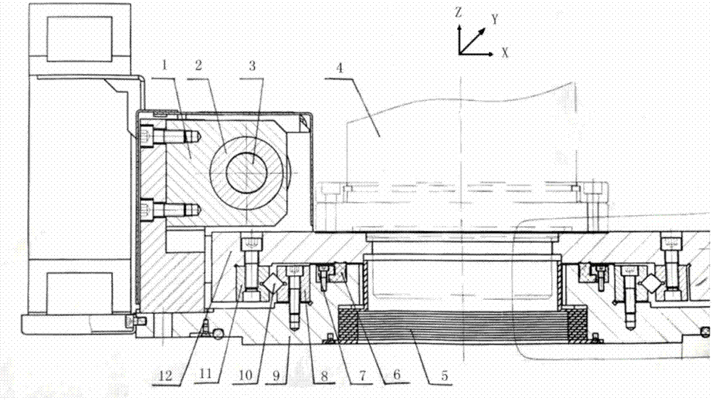
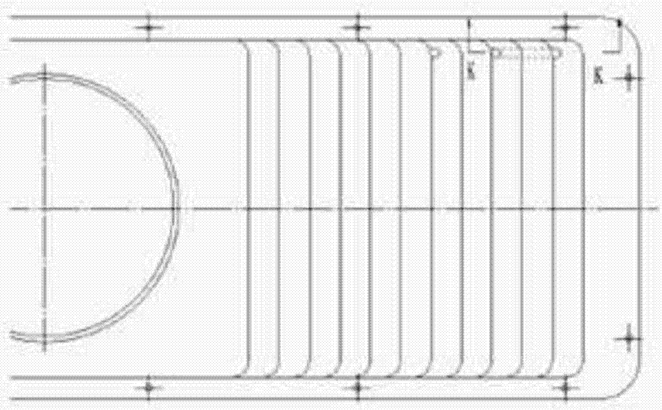
[0038] Such as Figure 1 to Figure 4 As shown, a linear partial dynamic seal motion mechanism with X-ray protection, the motion mechanism includes: a certain carriage 9, the fixed carriage 9 and the fixed guide rail 8 are connected by studs, and the The upper part of the fixed carriage 9 is provided with a movable carriage 12, and a movable guide rail 11 is installed below the movable carriage 12, and the movable carriage 12 is supported by rollers 10, so that the movable carriage 12 and the fixed carriage 9 The gap between 0.2-0.5mm is kept between, and the electron gun 4 is fixedly arranged on the moving carriage 12, and the electron gun 4 can move linearly along with the moving carriage 12; A stacked telescopic lead protection system 5 is arranged in the groove inside the plate 9, t...


PUM


Abstract

The invention disclose a linear partial motive sealing moving mechanism provided with an X-ray protection function. The moving mechanism comprises a static traction plate, wherein the static traction plate is connected with a static guide rail through a screw bolt; a movable traction plate is arranged on the upper part of the static traction plate; a movable guide rail is arranged on the low side of the movable traction plate; the movable traction plate is supported through pin rollers, so that a clearance of about 0.2-0.5 mm is preserved between the movable traction plate and the static traction plate; and an electronic torch is fixedly arranged on the movable traction plate, and can move linearly along with the movable traction plate. According to the linear partial motive sealing moving mechanism, an L-shaped concave-surface sealing ring is arranged, so that machining precision of a sealing groove is lowered; convex parts are arranged on two ends of the concave surface of the sealing ring, so that a double sealing effect is realized; sealing decrement can be reduced, and movement resistance of the sealing ring to the movable traction plate is reduced; and a laminated telescopic lead protection system is designed, so that X-rays generated during welding can be shielded in a full-movement stroke in the whole movement process of the electronic torch.

Description

technical field [0001] The invention relates to a sealing motion mechanism, in particular to a linear partial dynamic sealing motion mechanism with X-ray protection, which is used for electron beam processing equipment with all electron guns installed outside the vacuum chamber, such as multifunctional composite numerical control vacuum electron beam processing equipment, belonging to Vacuum electron beam equipment technology field. Background technique [0002] For vacuum electron beam welding equipment, especially large-scale equipment, when the electron gun is installed externally, the electron gun is usually installed on the top or side of the vacuum chamber, and a set of motion mechanism is designed between the vacuum chamber and the electron gun. Drive the electron gun for longitudinal movement, and realize the electron gun to seam or longitudinal welding movement by moving the electron gun. [0003] At present, the linear partial dynamic sealing motion mechanism desi...

Claims


Application Information

Patent Timeline
Patent Type & Authority Applications(China)
IPC IPC(8): B23K15/06B23K37/02
CPCB23K15/0046B23K15/06B23K37/0252
Inventor 黄以平宋宜梅李少林
Owner 桂林实创真空数控设备有限公司
Learn More