Plasmon refractive index sensor based on nano pattern and sensing method thereof

A technology of a refractive index sensor and a plasmon element, applied in the field of optical sensors, can solve problems such as limitation and complexity, and achieve the effects of high sensitivity, low preparation cost, and simple and mature preparation process

Active Publication Date: 2017-07-11
NANJING UNIV
View PDF8 Cites 10 Cited by
  • Summary
  • Abstract
  • Description
  • Claims
  • Application Information

AI Technical Summary

Problems solved by technology

However, these two plasmonic refractive index sensors require relatively complex spectral acquisition equipment and corresponding specially designed optical path systems, so that these two sensing technologies are widely used in fields such as real-time environmental monitoring and clinical rapid diagnosis. The application is very limited, because these fields require the sensing equipment to have good portability and certain sensitivity

Method used


Image

  • Plasmon refractive index sensor based on nano pattern and sensing method thereof
  • Plasmon refractive index sensor based on nano pattern and sensing method thereof
  • Plasmon refractive index sensor based on nano pattern and sensing method thereof

Examples


Embodiment 1

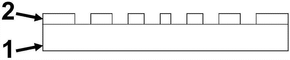
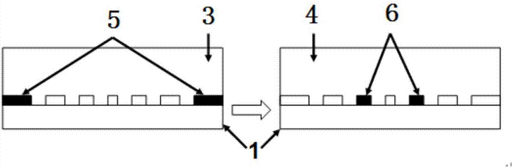
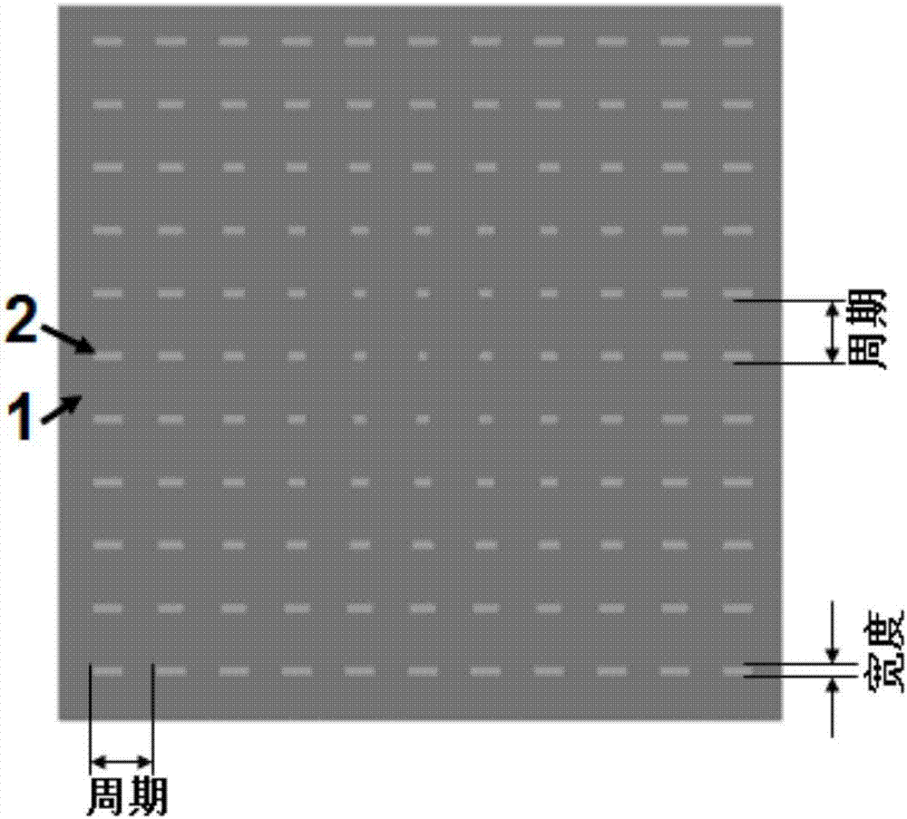
[0032] The plasmonic element refractive index sensor based on the nano-pattern of the present embodiment is covered with a plasmonic element nano-antenna array composed of a series of rectangular gold nano-antennas with different lengths on the quartz substrate, and the width of the nano-antenna is 50 Nanometer, the length gradually increases from the center to the periphery in an arithmetic sequence, and the length of the antenna increases by 1 nanometer for each additional circle, the period of the array is 300 nanometers, the length of the antenna at the center is 80 nanometers, and the length of the antenna at the outermost circle of the array is 200 nanometers nanometer, gold nanoantenna thickness is 45 nanometers (such as figure 1 , image 3 ).

[0033] The preparation method of the nano-pattern-based plasmonic refractive index sensor of this embodiment:

[0034] (1) Deposit a layer of gold with a thickness of 45 nanometers on a clean transparent quartz wafer by electr...

Embodiment 2

[0045] The nanopattern-based plasmonic refractive index sensor of this embodiment is covered with a plasmonic nanoantenna array composed of a series of circular silicon nanoantennas with different diameters on the silicon substrate. The diameter of the nanoantennas ranges from One end of the array gradually increases in proportion to the other end, and the diameter of the antenna increases by 1.05 times for each additional period. The diameter of the smallest circular antenna at one end of the array is 50 nanometers, and it gradually changes to the other end for 100 periods, with a period of 500 nanometers. Silicon The thickness of the nanoantenna is 60 nm (such as Figure 4 ).

[0046] The preparation method of the nano-pattern-based plasmonic refractive index sensor of this embodiment:

[0047] (1) Spin-coat a layer of negative photoresist with a thickness of 100 nanometers on a clean silicon wafer.

[0048] (2) Using interference lithography equipment to prepare the above...


PUM

PropertyMeasurementUnit
thicknessaaaaaaaaaa
wavelengthaaaaaaaaaa
thicknessaaaaaaaaaa

Abstract

The invention discloses a plasmon refractive index sensor based on a nano pattern and a sensing method thereof. The sensor comprises a layer of plasmon nano antenna array and a flat transparent substrate supporting the antenna array, the plasmon nano antenna array is a periodic array structure, the period is 50 to 1000 nanometers, and the thickness is 10 to 100 nanometers; the size of a single nano antenna of the array structure gradually changes according to a certain law, and the changing range is from 10 to 10000 nm. The sensor uses an imaging device to detect brightness and color change of a finite difference time domain method nano antenna array on the sensor in to-be-tested medium environment or position change of a resonance nano antenna under monochromatic light or white light irradiation to achieve medium refractive index sensing. The plasmon refractive index sensor has the advantages of simple detection technique, high sensitivity, good stability, low cost of needed detection equipment, and the like.

Description

technical field [0001] The invention belongs to the field of optical sensors, and in particular relates to a nano-pattern-based plasmonic element refractive index sensor and a sensing method thereof. Background technique [0002] As a low-cost and label-free biochemical detection technology, plasmonic refractive index sensor has attracted extensive attention from academia and industry in recent years. Among the plasmonic refractive index sensors, there are two main ones: LSPR sensors based on localized surface plasmon resonance and SPR sensors based on propagating mode surface plasmon resonance. [0003] For LSPR sensors, the change in the refractive index of the medium is achieved by measuring the shift of the resonant peak in the transmission or reflection spectrum. The earlier commercial application of the SPR sensor detects small changes in the refractive index by measuring the angle change on the surface of the reflected light substrate when the plasmon resonance occur...

Claims


Application Information

Patent Timeline
Patent Type & Authority Applications(China)
IPC IPC(8): G01N21/41G01N21/552
CPCG01N21/41G01N21/554
Inventor 张伟华边捷
Owner NANJING UNIV
Why Eureka
Try Eureka