
Linear array jet type FDM (fused deposition manufacturing) three-dimensional printing spray head and printing method

A 3D printing and jetting technology, applied in 3D object support structures, additive manufacturing, coating devices, etc., can solve problems such as limited nozzle flow, long running time, and huge total length, and achieve high work efficiency.

Inactive Publication Date: 2017-07-14
HUBEI UNIV OF TECH
View PDF11 Cites 2 Cited by
  • Summary
  • Abstract
  • Description
  • Claims
  • Application Information

AI Technical Summary

Problems solved by technology

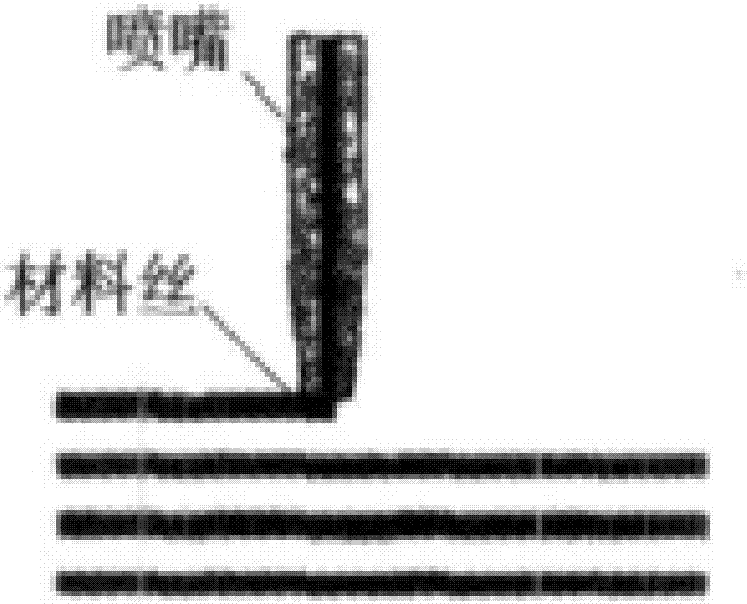
The U.S. patent "Multicolored Fused Deposition Modeling Print" (US9283714B2) discloses a color FDM nozzle design scheme and the principle of dyeing filaments, dyeing the raw material filaments before entering the nozzle, and then realizing color 3D printing; Chinese utility model patent "3D printing device The structure of nozzles” (201620114545.X) is the method of setting holes of different sizes on the ring gear, and nozzles with different apertures can be selected according to the part of the molding object or the size of the printing area; the utility model patent “a three-dimensional printing high-speed precision quantitative nozzle "(201520656239.4) is that the printing needle is attracted by the electromagnet in the form of piston movement to realize the small hole injection of a small amount of liquid; the utility model patent "A 3D printer nozzle with adjustable extrusion flow rate" (201520336155.2) is in The cross-section of the nozzle at the end of the nozzle is set to be rectangular, and at the same time, a nozzle piston groove with a T-shaped cross-section is set on the side of the nozzle. Through the movement of the piston in the piston groove, the dynamic adjustment of the cross-sectional area of ​​the rectangular outlet is realized. In essence, it is still a hole-type nozzle with a single outlet. Although the cross-section filling efficiency can be improved by thin-ribbon spraying, the cross-section of the ejected flat thin strip is a solid, narrow and long rectangle, and the nozzle itself must also rotate at the position of the turning path to keep the ejected strip always perpendicular to the tangential direction of the trajectory , that is, the nozzle still needs to follow the straight line / curve filling trajectory of the cross-sectional profile of the workpiece to complete the complex trajectory movement with a total length and a huge time-consuming; the utility model patent "Extrusion nozzle structure of rapid prototyping system" (98219118.9) discloses a small The design of the relief valve is set at the position of the hole to realize the stability of the melt pressure inside the nozzle
[0005] The prior art disclosed above has the following deficiencies in the FDM nozzle and the injection molding principle: 1. The small hole sprays the melt to complete the point filling of the two-dimensional cross-sectional shape, and the flow rate of the nozzle hole is extremely limited, which directly brings accuracy The contradiction with efficiency is the source of the key defect of FDM 3D printing technology; 2. Relying on the point trajectory scanning of the tip of the nozzle to complete the solid shape, the total length of the actual running trajectory of the nozzle is extremely huge, and the running time is extremely lengthy; 3. The output per unit time The material speed is limited, which is not suitable for the printing needs of large-size components

Method used


Image

  • Linear array jet type FDM (fused deposition manufacturing) three-dimensional printing spray head and printing method
  • Linear array jet type FDM (fused deposition manufacturing) three-dimensional printing spray head and printing method
  • Linear array jet type FDM (fused deposition manufacturing) three-dimensional printing spray head and printing method

Examples


Embodiment Construction

[0033] The embodiments of the present invention will be further described below in conjunction with the accompanying drawings. Examples of the embodiments are shown in the accompanying drawings, wherein the same or similar symbols throughout represent the same or similar elements or elements with the same or similar functions. The following embodiments of the present invention are only used to illustrate or explain the principle of the present invention, but not to limit the present invention. Any modifications, equivalent replacements, improvements, etc. made without departing from the spirit and scope of the present invention shall fall within the protection scope of the present invention. Furthermore, it is intended that the appended claims of the present invention embrace all changes and modifications that come within the scope and metesques of the appended claims, or equivalents of such scope and metes and bounds. For clarity of illustration, the following description omi...


PUM


Abstract

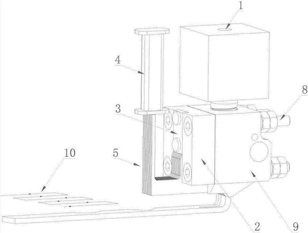
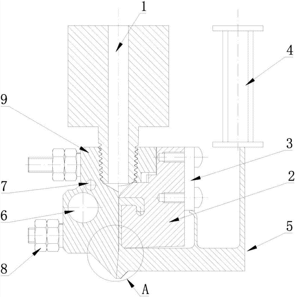
The invention discloses a linear array jet type FDM (fused deposition manufacturing) three-dimensional printing spray head and a printing method. The spray head comprises a spray head main body, a spray head mask, a sliced blocking needle array, a blocking needle pressure adjustment block and a blocking needle array drive device. A spray nozzle is internally provided with a long-narrow-seam-shaped molten printing material flowing-out opening, and flat molten plastic jet flow of a set width is formed; the sliced blocking needle array is formed by stacking a plurality of sliced blocking needles, and the planar structures of all the sliced blocking needles are the same in shape and the same or different in thickness; the blocking needle array drive device is used for driving any sliced blocking needle to swing front and back, and when the molten plastic jet flow of the width of the position where any sliced blocking needle is located is blocked or opened, the molten plastic jet flow is made to generate position-controllable comb-shaped gaps; and the three-dimensional printing spray head performs reciprocating linear movement according to the track shaped like a Chinese character 'ji', the comb-shaped controllable flat molten plastic jet flow is spread and laid on a worktable top to be deposited to form set patterns, and multiple layers of the patterns are piled to form a three-dimensional printing workpiece.

Description

technical field [0001] The present invention relates to a line-array jetting type FDM three-dimensional printing nozzle and a printing method, in particular to a design of a line-array jetting type nozzle for an FDM three-dimensional printer, and belongs to the technical field of rapid prototyping and three-dimensional printers. Background technique [0002] FDM (Fused Deposition Manufacturing) was invented by Kurt Crump of the United States in 1988. It is a kind of plastic wire that is fed into the print head to melt. The path controlled by computer instructions is filled with melt-plastic thin lines to realize the layered and superimposed molding of three-dimensional objects. Among them, the nozzle is the key component to achieve fusion deposition molding, and it is also the core of the FDM 3D printer. The nozzle generally includes a raw material feeding device, a plasticizing device, a nozzle, a feeding drive device and a controller; the driving device is for adding raw m...

Claims


Application Information

Patent Timeline
Patent Type & Authority Applications(China)
IPC IPC(8): B29C64/118B29C64/209B33Y30/00B33Y10/00
CPCB33Y10/00B33Y30/00
Inventor 张铮范良志江珂
Owner HUBEI UNIV OF TECH
Learn More