Magnetic suspension gravity compensator

A technology of gravity compensation and magnetic levitation, which is applied in the field of magnetic levitation, can solve problems such as complex structure of the device, and achieve the effects of small force fluctuation, low loss, and high force density

Active Publication Date: 2017-07-14
HARBIN INST OF TECH
View PDF4 Cites 12 Cited by
  • Summary
  • Abstract
  • Description
  • Claims
  • Application Information

AI Technical Summary

Problems solved by technology

[0005] The present invention is to solve the problem that the air spring is used as the gravity compensation device, and the device structure is complicated when it is applied in a vacuum environment. The present invention provides a magnetic suspension gravity compensator, which includes two sets of solutions

Method used


Image

  • Magnetic suspension gravity compensator
  • Magnetic suspension gravity compensator
  • Magnetic suspension gravity compensator

Examples


specific Embodiment approach 1

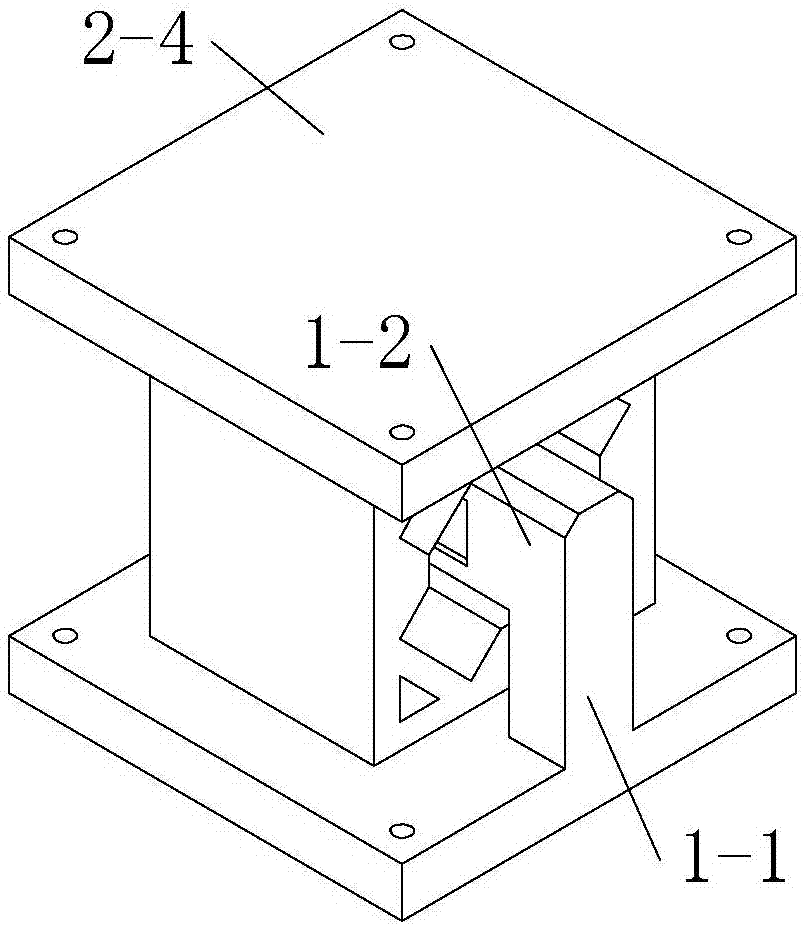
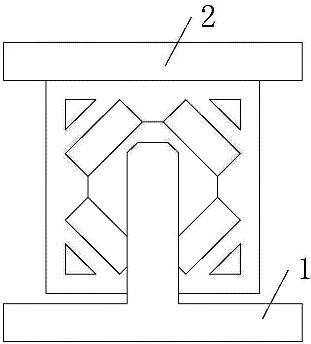
[0053] Specific implementation mode one: see Figure 1 to Figure 3 ,and Figure 23 and Figure 24 Describe this embodiment, the magnetic levitation gravity compensator described in this embodiment, it comprises a stator 1 and a mover 2;

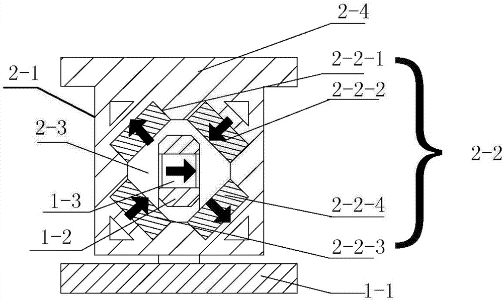
[0054]Stator 1 includes stator frame 1-1, stator beam 1-2 and stator permanent magnet 1-3; the number of stator permanent magnet 1-3 is 1 or 2, when the number of stator permanent magnet 1-3 is 1, The stator permanent magnet 1-3 is embedded in the stator beam 1-2, and the two are coaxial. When the number of the stator permanent magnet 1-3 is 2, two stator permanent magnets 1-3 are respectively embedded in the stator beam 1. The upper, lower or left and right surfaces of -2; the stator beam 1-2 is fixed on the stator frame 1-1;

[0055] The mover 2 includes a mover frame 2-1 and a mover base 2-4, the mover frame 2-1 is fixed on the lower surface of the mover base 2-4, and a mover permanent magnet is arranged inside the mover frame 2-1 A di...

specific Embodiment approach 2

[0073] Specific implementation mode two: see Figure 1 to Figure 6 , Figure 23 and Figure 24 Describe this embodiment, the difference between this embodiment and the magnetic levitation gravity compensator described in Embodiment 1 is that the stator 1 also includes two sets of stator coils 1-4; the two sets of stator coils 1-4 are rectangular structures, And it is symmetrically embedded in the left and right surfaces of the stator beam 1-2, and runs through the cavity 2-3.

[0074] For details, see Figure 6 , when the number of stator permanent magnets 1-3 is 1, the magnetic levitation gravity compensator utilizes the interaction force between the stator permanent magnets 1-3 and the mover permanent magnet rhombic array and the interaction between the stator coils 1-4 and the mover The interaction force between the magnetic fields generated by the rhombic array of sub-permanent magnets realizes magnetic levitation and compensation for gravity;

[0075] Stator permanent...

specific Embodiment approach 3

[0088] Specific implementation mode three: see Figure 1 to Figure 7 , Figure 23 and Figure 24 Describe this embodiment. The difference between this embodiment and the magnetic levitation gravity compensator described in Embodiment 1 or 2 is that it also includes N stators 1 and N movers 2; N+1 movers 2 move along the Y axis It is arranged in series in the direction, and a stator beam 1-2 is correspondingly provided in the cavity 2-3 of each mover 2, N+1 mover bases 2-4 are integrated, and N+1 stator frames 1- The base of 1 is one piece, and N is an integer greater than or equal to 1.


PUM


Abstract

Provided is a magnetic suspension gravity compensator, belonging to the technical field of magnetic suspension and solving the problem that an air spring is taken as a gravity compensating device, so that the device is complex in structure while being applied to a vacuum environment. The magnetic suspension gravity compensator includes a stator and a mover, an air gap is arranged between the stator and the mover, the stator includes a stator frame, a stator cross beam, and a stator permanent magnet, the mover includes a mover frame and a mover base, the mover frame is fixed to the lower surface of the mover base, the inside of the mover frame is provided with a mover permanent magnet rhombus array, the mover permanent magnet rhombus array is composed of four mover permanent magnets, the mover permanent magnet rhombus array forms a cavity, and the stator cross beam penetrates through the cavity. The compensation of the motion quality in the magnetic suspension system is achieved by the mutual active force between magnetic fields generated by the mutual active force between the stator permanent magnet and the mover permanent magnet rhombus array, so that the magnetic suspension can be realized. The magnetic suspension gravity compensator is applied to gravity compensation.

Description

technical field [0001] The invention belongs to the technical field of magnetic suspension. Background technique [0002] Magnetic levitation technology has the advantages of no mechanical contact, no friction, no wear, and no lubrication, so it is considered to be the most advanced technology for testing and processing in a vacuum environment, and has broad application prospects in ultra-precision testing and processing equipment. In general, magnetic levitation can be achieved by controlling six degrees of freedom motion using multiple actuators and sensors. However, in the process of levitation and positioning, in order to support the moving mass, the actuator needs to be continuously energized to work, and the heat generated will cause problems of environmental temperature rise and mechanical deformation. Therefore, it is very necessary to set up a gravity compensation device with excellent performance for the magnetic levitation system. [0003] At present, air spring...

Claims


Application Information

Patent Timeline
IPC IPC(8): H02N15/00
CPCH02N15/00
Inventor 寇宝泉周一恒张赫张鲁
Owner HARBIN INST OF TECH
Why Eureka
Try Eureka