
Microphone structure and manufacturing method thereof

A manufacturing method and microphone technology, which is applied in the direction of electrostatic transducer microphones, sensors, electrical components, etc., can solve the problems that the performance of MEMS microphones needs to be improved, and achieve the effect of increasing the amount of change and improving sensitivity

Active Publication Date: 2017-07-14
SEMICON MFG INT (SHANGHAI) CORP +1
View PDF4 Cites 15 Cited by
  • Summary
  • Abstract
  • Description
  • Claims
  • Application Information

AI Technical Summary

Problems solved by technology

[0004] But, the performance of the MEMS microphone that prior art forms remains to be improved

Method used


Image

  • Microphone structure and manufacturing method thereof
  • Microphone structure and manufacturing method thereof
  • Microphone structure and manufacturing method thereof

Examples


Embodiment Construction

[0031] It can be seen from the background art that the performance of the microphone formed in the prior art needs to be optimized.

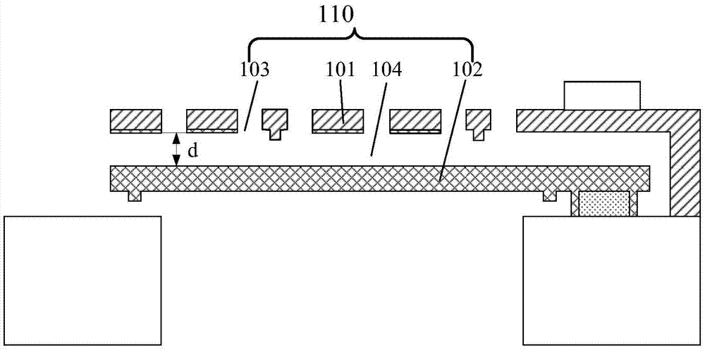
[0032] refer to figure 1 , figure 1 A schematic structural diagram of a microphone in the prior art is shown. The function of the microphone is realized by a capacitive structure 110 . The capacitive structure 110 mainly includes a diaphragm 102, a back plate 101, a cavity 104 between the diaphragm 102 and the back plate 101, and an acoustic hole 103 in the back plate 101. The diaphragm 102 and the back plate Plate 101 is used to form a capacitive plate. Air enters the cavity 104 through the sound hole 103 , and the air pressure generated by the sound causes the vibration of the diaphragm 102 , thereby changing the capacitance and finally causing a change in voltage. Among them, the parameters affecting the capacitance value mainly include the effective area of ​​the capacitive plates (ie, the diaphragm 102 and the back plate 101 ) and the d...


PUM

PropertyMeasurementUnit
Diameteraaaaaaaaaa
Heightaaaaaaaaaa
Thicknessaaaaaaaaaa

Abstract

The invention discloses a microphone structure and a manufacturing method thereof. The method comprises the following steps: providing a substrate which comprises a first surface; forming a vibrating membrane on the first surface and multiple discrete columnar bulges bulged on the vibrating membrane surface so as to form a vibrating membrane structure; forming a backboard structure above the vibrating membrane structure, wherein multiple sound holes are formed on the backboard, multiple sound holes penetrate the backboard structure and are in one-to-one correspondence to the columnar bulges, and partial high columnar bulges are located in the sound holes. Multiple discrete columnar bulges bulged on the vibrating membrane surface are formed, when partial high columnar bulges are located in the sound holes, the vibrating membrane vibrates along the vibration of the air pressure, and the distance between the vibrating membrane structure and the backboard structure is changed, the multiple discrete columnar bulges increase the active area variation between the vibrating membrane structure and the backboard structure, thereby increasing the variation of a capacitance value, and then increasing the variation of an output voltage to improve the sensitivity of the microphone.

Description

technical field [0001] The invention relates to the field of semiconductors, in particular to a microphone structure and a manufacturing method thereof. Background technique [0002] A microphone is a conversion device that converts sound signals into electrical signals. It is a crucial device in an electroacoustic system. The performance of the microphone directly affects the sound quality of the electroacoustic system. With the development of wireless communication and multimedia technologies, microphones have been developed from electret capacitor microphones (Electret Capacitance Microphone, ECM) to micro electromechanical system (Micro Electro Mechanic System, MEMS) microphones. [0003] MEMS microphones are microphones based on MEMS technology. Compared with electret condenser microphones, MEMS microphones have stronger heat resistance, vibration resistance, and radio frequency interference capabilities. In order to meet the needs of portable electronic products With ...

Claims


Application Information

Patent Timeline
IPC IPC(8): H04R19/04H04R31/00
CPCH04R19/04H04R31/00
Inventor 王强石慧曾笑梅许谢慧娜
Owner SEMICON MFG INT (SHANGHAI) CORP
Learn More