Rubber dynamic injection moulding device and method

An injection molding device and rubber injection technology, which is applied in the field of rubber dynamic injection molding devices, can solve the problems of reducing rubber viscosity, poor fluidity, and difficult molding, and achieve the effect of changing fluidity and reducing energy consumption

Active Publication Date: 2017-07-18
QINGDAO UNIV OF SCI & TECH
View PDF9 Cites 4 Cited by
  • Summary
  • Abstract
  • Description
  • Claims
  • Application Information

AI Technical Summary

Problems solved by technology

[0003] The traditional molding method usually uses a screw plunger injection machine or a screw reciprocating injection machine to form rubber products. This technology is used for the molding of rubber products with small size and short length. If the quality of rubber products increases and the length increases, Due to the obvious elasticity of rubber, large flow resistance, and high viscosity, it is difficult to fill large-scale rubber products at one time. The plasticized rubber needs to be injected repeatedly to fill the mold cavity, which will cause the uniformity of the product to decrease and the surface quality to be poor. and other defects; or the use of large-scale injection equipment will bring about the disadvantages of high injection pressure, bulky equipment, and high energy consumption. There are also many reports that vibration is applied to the molding process during the plastic extrusion molding process. For example, Chinese patent ZL201320792167.7 discloses a vibrating injection molding machine. In this patent, a set of axial vibration device is connected to the tail of the screw. The axial vibration force is directly transmitted to the screw, and then the axial vibration is transmitted to the entire barrel through the screw. Although both rubber and plastic are polymer materials, there are typical differences between them: (1) molecular structure and molecular weight distribution are different; rubber is mostly non-polar polymer, The molecular chain mostly contains double bonds, the molecular weight is larger than that of plastic, and the molecular weight distribution is wider than that of plastic; the molecular chain of rubber is short and has many links, and its flexibility is better than that of plastic, with large deformation and high elasticity. swelling behavior is obvious
(2) The flow viscosity of rubber is higher than that of plastic, the fluidity is poor, and the molecular weight reaches 10 5 Above, the intermolecular force increases, the molecular chain movement overcomes the resistance increase, and the flow is difficult, so it is much more difficult to mold with rubber materials than plastic molding.
[0004] According to the rheological properties of rubber, the reason why rubber molecules can flow is that there is a space for free activities. The free space volume of molecular chains is directly related to the pressure. When the pressure is high, the free space volume decreases, which hinders the molecular activities, and the mobility of the chains is reversed. Decrease, on the contrary, will reduce the fluidity of the rubber, so the existing technology does not fundamentally change the fluidity of the rubber, reduce the viscosity of the rubber, which is not conducive to the limited reduction of the energy consumption of the mold filling; the present invention also tries to superimpose the vibration of the plastic The way of field is applied to rubber molding technology, but after countless tests and designs, the inventor found that the equipment and method of vibration application in plastic processing are not ideal for rubber, and even once gave up applying vibration field to rubber injection The initial effort of molding, and precisely because of the obvious difference between the two materials, did not apply vibration technology to the rubber molding process in previous papers and patents. However, as the experiment progressed, we obtained a An injection molding device and method, the device and method can fundamentally improve rubber fluidity, increase rubber filling capacity, reduce injection pressure, save energy consumption, reduce production costs and improve the quality of rubber products

Method used


Image

  • Rubber dynamic injection moulding device and method
  • Rubber dynamic injection moulding device and method
  • Rubber dynamic injection moulding device and method

Examples


Embodiment 1

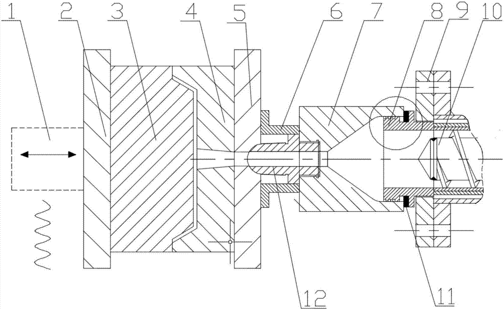
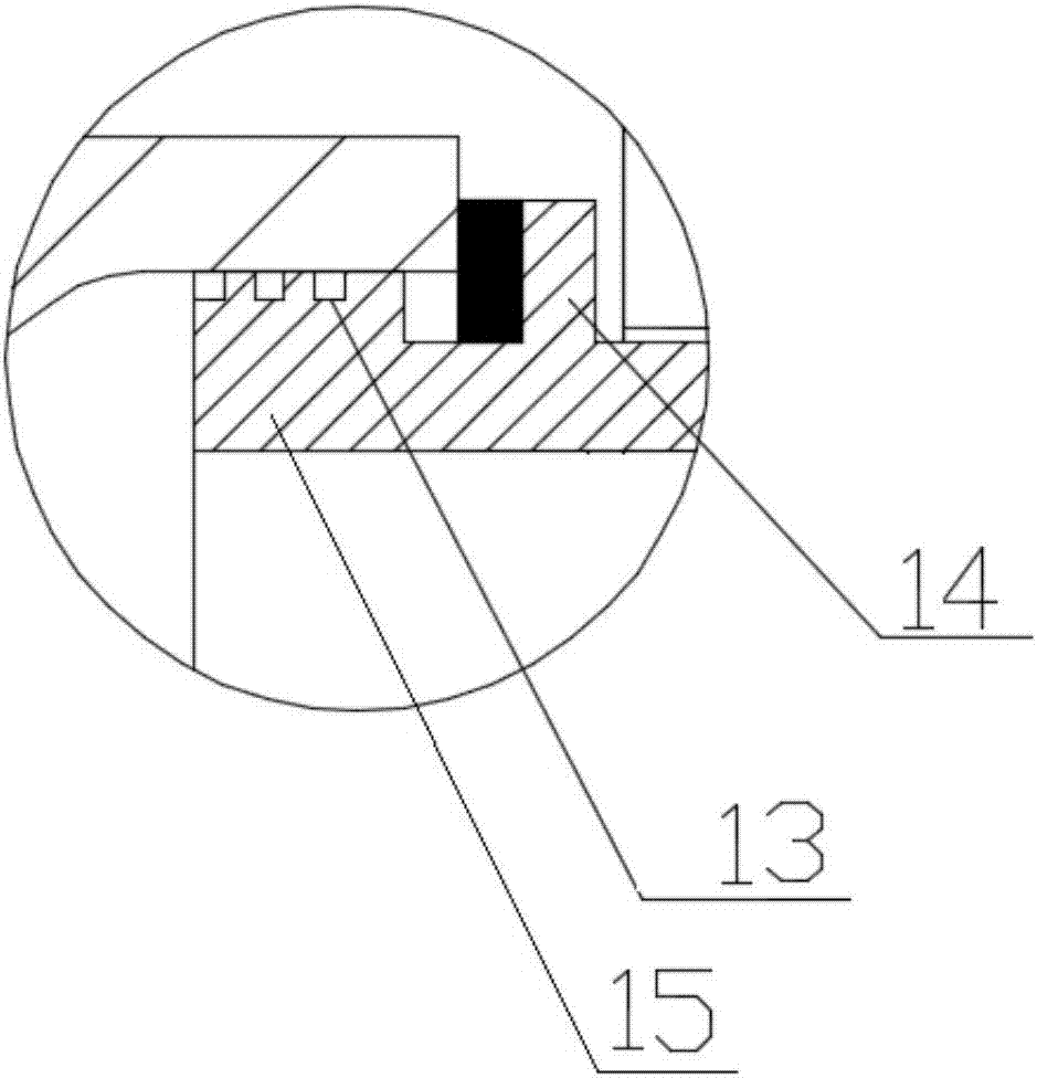
[0036] Such as figure 1 As shown, a rubber dynamic injection molding device includes a rubber cold-feed screw extruder 10, a slip ring 8, a vibrating sleeve 7, an injection nozzle 12, an upper backing plate 5, an upper template 4, a lower template 3, The lower backing plate 2 and the electro-hydraulic hydraulic vibration system 1, wherein the vibration sleeve 7 is a cavity structure with cylindrical ends and a truncated cone in the middle, the slip ring 8 is a hollow sleeve structure, and one end of the slip ring 8 The connecting ring 9 is screwed and fixedly connected with the rubber cold feed screw extruder 10. A first flange 15 is provided on the circumference of the other end side, and a second flange 14 is provided on the outer circumference. The first flange 15 is connected to the second flange. The distance between the flanges 14 is 20-25mm, the first flange 15 is in clearance fit with the front end of the vibrating sleeve 7, and the gap between the first flange 15 and ...

Embodiment 2

[0038] (1) 70 parts by weight of raw rubber TSR20 and 30 parts by weight of raw rubber BR9000, 2 parts by weight of raw rubber small material SAD, 4 parts by weight of ZnO and 4010NA of 1 part by weight, carbon black N375 of 40 parts by weight, 25 parts by weight Aromatic hydrocarbon oil in parts by weight, carbon black remaining 20 parts by weight are heated and mixed in the internal mixer to make it uniform, the heating temperature is 110 ℃, and the mixing time is 9min, then add 1.8 parts by weight of vulcanizing agent in the open mixer S and 0.9 parts by weight of CZ, continue mixing, the total mixing time is 20min, and the rubber material after mixing is parked for 24h;

[0039] (2) The temperature of the feeding section, plasticizing section and extrusion section of the rubber cold-feeding screw extruder is controlled at 50°C, 65°C and 75°C in sequence, and the screw temperature is set at 80°C. The role of the injection mold in the temperature control system Heat it up to...

Embodiment 3

[0043] (1) 70 parts by weight of raw rubber TSR20 and 30 parts by weight of raw rubber BR9000, 2 parts by weight of raw rubber small material SAD, 4 parts by weight of ZnO and 4010NA of 1 part by weight, carbon black N375 of 40 parts by weight, 25 parts by weight Aromatic hydrocarbon oil in parts by weight, carbon black remaining 20 parts by weight are heated and mixed in the internal mixer to make it uniform, the heating temperature is 100 ℃, and the mixing time is 5min, then add 1.8 parts by weight of vulcanizing agent in the open mixer S and 0.9 parts by weight of CZ, continue mixing, the total mixing time is 5min, and the rubber material after mixing is parked for 30h;

[0044] (2) The temperature of the feeding section, plasticizing section and extrusion section of the rubber cold-feeding screw extruder is controlled at 50°C, 65°C and 75°C in sequence, and the screw temperature is set at 80°C. The role of the injection mold in the temperature control system Heat it up to ...


PUM

PropertyMeasurementUnit
thicknessaaaaaaaaaa

Abstract

The invention belongs to the field of moulding manufacturing of rubber products, and discloses a rubber dynamic injection moulding device and method. The device comprises a rubber cold feeding screw extruder, a sliding ring, a vibration sleeve, an injection nozzle, an upper cushion plate, an upper form board, a lower form board, a lower cushion plate and an electro-hydraulic hydraulic vibration system which are connected in sequence. According to the device, a vibration field is stacked at the position of an injection mold. According to the method, on the basis of not changing the mold structure and the material formula, the vibration field is stacked in the main shear direction of rubber to change the fluidity of rubber materials. According to the dynamic injection moulding device and method, the rubber filling capacity can be enhanced, injection pressure can be reduced, energy consumption can be reduced, and product quality can be improved; and especially it is possible to moulding the large-size and high-quality rubber products.

Description

technical field [0001] The invention relates to the molding and manufacturing of rubber products, in particular to a rubber dynamic injection molding device and method. Background technique [0002] Rubber injection molding products have the characteristics of high compactness, accurate dimensional accuracy, excellent performance, and high productivity, making them widely used in industry, agriculture, national defense, transportation, transportation, machinery manufacturing, medical and health fields and daily aspects of life. With the development of scientific and technological progress, the advancement of automobiles, aviation, national defense, and cutting-edge technology has put forward higher and higher requirements for rubber products, and rubber products are developing in the direction of large size, high quality, and complex cross-sectional shapes. [0003] The traditional molding method usually uses a screw plunger injection machine or a screw reciprocating inject...

Claims


Application Information

Patent Timeline
Patent Type & Authority Applications(China)
IPC IPC(8): B29C45/58B29C45/77B29C45/78
CPCB29C45/585B29C45/77B29C45/78B29C2945/76531B29C2945/76665B29C2945/76605
Inventor 焦冬梅边慧光
Owner QINGDAO UNIV OF SCI & TECH
Why Eureka
Try Eureka