A cartridge separation device for a large submersible deep underwater non-powered launch delivery system

A separation device and launcher technology, applied in torpedo launchers, offensive equipment, weapon types, etc., can solve problems such as the inability to meet the sealing requirements, the problem of heat protection of the launcher, and the complex structure, so as to solve the problem of heat protection and avoid long-term problems. Time wash, improve concealment effect

Active Publication Date: 2018-11-27
THE GENERAL DESIGNING INST OF HUBEI SPACE TECH ACAD
View PDF3 Cites 1 Cited by
  • Summary
  • Abstract
  • Description
  • Claims
  • Application Information

AI Technical Summary

Problems solved by technology

[0003] The cartridge separation device is used in the way of ejection and ejection, and the gas-steam separation method is generally used. The cartridge separation device is mainly composed of a launcher, a gas generator, a cooler, and a sealing ring. The gas flow of the gas launcher and the cooler The water inside is fully heat-exchanged to form a mixed steam that enters the initial chamber of the launch tube and drives the missile to move. This type of tube separation device requires a special cooler for cooling, which has a complex structure and a large volume. If the cooler is removed for direct Gas ejection, heat protection in the launch tube is a problem
When the missile barrel is separated, it relies on the sealing ring for steam sealing, but this sealing method is only suitable for the smooth structure of the outer surface of the missile and the inner wall of the launching barrel. Empennage, sealing ring method will not meet the sealing requirements
In addition, the current underwater missile launcher is for one-time use, and the launcher sinks into the bottom of the water after the missile is launched, which is not conducive to reducing costs

Method used


Image

  • A cartridge separation device for a large submersible deep underwater non-powered launch delivery system
  • A cartridge separation device for a large submersible deep underwater non-powered launch delivery system
  • A cartridge separation device for a large submersible deep underwater non-powered launch delivery system

Examples


Embodiment

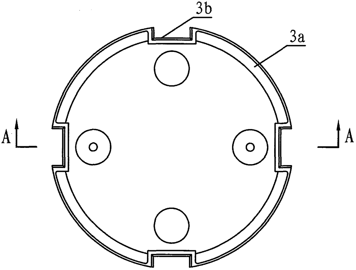
[0019] Such as figure 1 It is a structural schematic diagram of the cartridge separating device of the large submerged deep underwater unpowered launch delivery system of the present invention, including a launch tube 1 provided with a front cover 1a, a sealing base plate 3 arranged in the launch tube 1, and a catapult 2. The catapult 2 is Gas generator, the jet is pure gas, the catapult 2 is fixed on one side of the sealed bottom plate 3, the other side of the sealed bottom plate 3 is attached to the tail end of the missile 5 (the missile 5 is installed in the launch tube 1), and the sealed bottom plate 3 can slide along the launch tube 1, and the launch tube 1 is also equipped with a cover opening mechanism 1b for opening the front cover 1a. The thrust generated by the catapult 2 pushes the sealing bottom plate 3 and then pushes the tail end of the missile 5 to make the missile 5 cover forward along the launch tube 1 Sliding in the direction of 1a, the missile 5 slides and s...


PUM


Abstract

The invention discloses a missile and barrel separation device of a high-submergence-depth underwater unpowered launching carrying system. The missile and barrel separation device comprises a launching barrel provided with a front cover, a sealing bottom plate arranged in the launching barrel and a catapult. The catapult is fixed to one side of the sealing bottom plate, and the other side of the sealing bottom plate is attached to the tail end of a guided missile. The sealing bottom plate can slide along the launching barrel. The launching barrel is further provided with a cover opening mechanism for opening the front cover. Pushing force generated by the catapult pushes the sealing bottom plate to further push the tail end of the guided missile so that the guided missile can slide towards the front cover along the launching barrel, and the guided missile slides to be separated out of the launching barrel. According to the missile and barrel separation device, the guided missile is placed in the launching barrel in an airtight manner; after the launching barrel comes out of water and reaches a set height and posture, a carrier sends out an instruction, the catapult works, the pushing force of the catapult acts on the sealing bottom plate to enable the guided missile to be popped out of the launching barrel, missile and barrel separation is achieved, and the sealing plate can be left in the launching barrel; the short-time watertight function of the launching barrel is achieved, and the launching barrel can float on the water surface; and launching barrel recycling is achieved, and cost is reduced.

Description

technical field [0001] The invention belongs to the technical field of separation of an underwater non-powered launching and carrying system, and in particular relates to a separating device for a large-submerged deep underwater non-powered launching and carrying system. Background technique [0002] The underwater non-powered launch delivery system includes a carrier and an aircraft (missile) equipped with a launch tube. There are generally two forms of missile launch. One is that the missile is directly ignited and launched in the launch tube, and the second is that the missile is launched in the launch tube. After the cylinder is ejected by the cartridge separation device in the barrel, it is ignited and launched, that is, ejected from the barrel. At present, most of them adopt the second method. [0003] The cartridge separation device is used in the way of ejection and ejection, and the gas-steam separation method is generally used. The cartridge separation device is ma...

Claims


Application Information

Patent Timeline
Patent Type & Authority Patents(China)
IPC IPC(8): F41F3/10
CPCF41F3/10
Inventor 张新朋郑玮李秀珍李华陈平龙垚松周祥熊俊宋毫
Owner THE GENERAL DESIGNING INST OF HUBEI SPACE TECH ACAD
Why Eureka
Try Eureka