Device for coupling spatial light with optical fiber

A technology of spatial light and optical fiber, applied in the field of optics, can solve problems such as multi-system space, and achieve the effects of high coupling efficiency, small volume requirements, and reduced space requirements

Pending Publication Date: 2017-07-18
莱特巴斯光学仪器(镇江)有限公司
View PDF10 Cites 1 Cited by
  • Summary
  • Abstract
  • Description
  • Claims
  • Application Information

AI Technical Summary

Problems solved by technology

Since the transmission of the light beam needs to ensure the best spot shape and the highest couplin...

Method used


Image

  • Device for coupling spatial light with optical fiber
  • Device for coupling spatial light with optical fiber
  • Device for coupling spatial light with optical fiber

Examples


Embodiment Construction

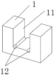
[0015] see Figure 1 to Figure 5 , a device for coupling spatial light into an optical fiber, comprising a concave samarium cobalt magnet 1, the samarium cobalt magnet 1 has a mounting groove 11, and the bottom of the mounting groove 11 is provided with a glue guide groove 12 to prevent the beam from shifting due to temperature expansion, There are two glue guide grooves 12, which are respectively located on both sides of the bottom of the installation groove 11. The two glue guide grooves 12 are parallel to each other, and the shape of the glue guide grooves is a semicircular groove.

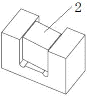
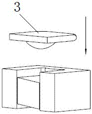
[0016] A single-stage isolator 2 is provided in the mounting groove 11, and a coupling lens 3 is provided above the single-stage isolator 2. The coupling lens 3 is square, and the single-stage isolator 2 is a hexahedron. The two inner walls are in contact with each other. The coupling lens 3 includes a spherical surface S1 and a plane S2. Both the top and bottom surfaces of the single-stage iso...


PUM

PropertyMeasurementUnit
Thicknessaaaaaaaaaa

Abstract

The invention relates to a device for coupling spatial light with an optical fiber. The device comprises a recessed samarium cobalt magnet. The samarium cobalt magnet is provided with a mounting trough. The bottom of the mounting trough is provided with a glue guiding trough. The mounting trough is internally provided with a single-order isolator. A coupling lens is arranged above the single-order isolator. The single-order isolator is a hexahedron. The side surface of the single-order isolator contacts with two inner walls of the mounting trough. The coupling lens comprises a spherical surface and a flat surface. An included angle between the top surface of the single-order isolator flat surface and an included angle between the bottom surface of the single-order isolator and the flat surface are 6-8 DEG. The spherical surface is next to the side of the single-order isolator. The single-order isolator does not contact with the top point of the spherical surface of the coupling lens. The physical aperture of the coupling lens at the spherical surface side is smaller than the optical aperture of the single-order isolator. The lens center of the coupling lens is coaxial with the optical center of the single-order isolator. The device provided by the invention has advantages of small size, effective process simplification and effective random error reduction. An optical isolating function and a coupling function are integrated in the device with total thickness which does not exceed 1.4mm, thereby satisfying requirements of maximal coupling efficiency and smallest size.

Description

technical field [0001] The invention relates to the field of optics, in particular to a device for coupling spatial light into an optical fiber. Background technique [0002] In the application of optical communication signal transmission, it is often necessary to couple near-infrared spatial light into optical fibers, and for the stability of signal transmission, it is necessary to add an optical isolator in this process. Communication customers need to design free space isolators, coupling lenses, and optical fibers sequentially in the optical system. Since the transmission of the light beam needs to ensure the best spot shape and the highest coupling efficiency, it requires more system space, more debugging and assembly time, and more many random errors. Contents of the invention [0003] The object of the present invention is to provide a device for coupling spatial light into an optical fiber with small volume and convenient assembly. [0004] The present invention...

Claims


Application Information

Patent Timeline
IPC IPC(8): G02B6/27G02B6/32
CPCG02B6/2746G02B6/32
Inventor 衣丽霞岳晖梅珊珊
Owner 莱特巴斯光学仪器(镇江)有限公司
Why Eureka
Try Eureka