Spoke air hole machining die

A technology for processing molds and spokes, which is applied in the field of stamping processing, can solve problems such as the inability of the stamping machine to work continuously, scratches on the inner wall of the spokes, and affect the processing efficiency, and achieve the effects of avoiding deformation, accelerating heat dissipation, and reducing labor intensity

Active Publication Date: 2017-07-21
重庆鼎汉巅宏汽车零部件有限公司
View PDF5 Cites 4 Cited by
  • Summary
  • Abstract
  • Description
  • Claims
  • Application Information

AI Technical Summary

Problems solved by technology

[0004] Yet this patent also has the following problems: 1. In order to punch the air holes, the spokes are fixed on the inclined wheel disc, and then punched by the punch of the upper die. After punching, the spokes need to be rotated. During the rotation of the spokes, the inner walls of the spokes rub against the stamped bumps, which may easily cause scratches on the inner walls of the spokes
2. After one punching, the punch is reset, and then the wheel needs to be turned artificially. After the spokes are rotated through a certain angle, they are locked and positioned by the pawl, and then the punching is performed again, which is very troublesome. During this process, the punching machine cannot Continuous work greatly affects processing efficiency

Method used


Image

  • Spoke air hole machining die
  • Spoke air hole machining die
  • Spoke air hole machining die

Examples


Embodiment Construction

[0022] The present invention will be described in further detail below by means of specific embodiments:

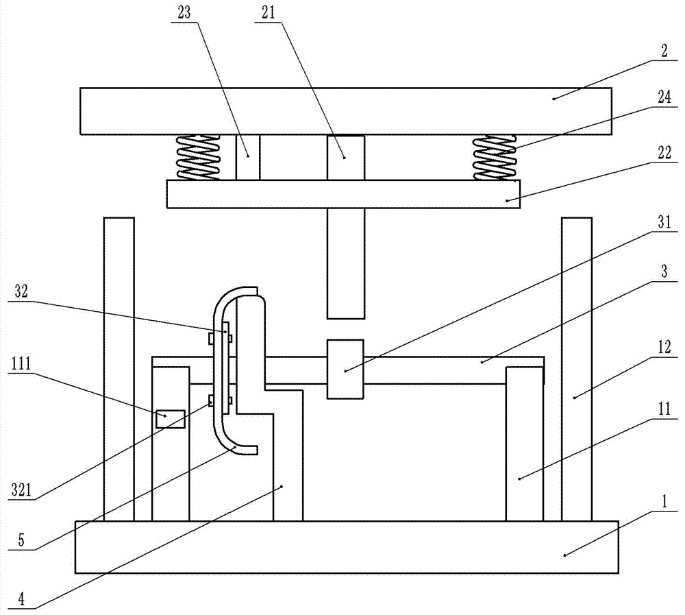
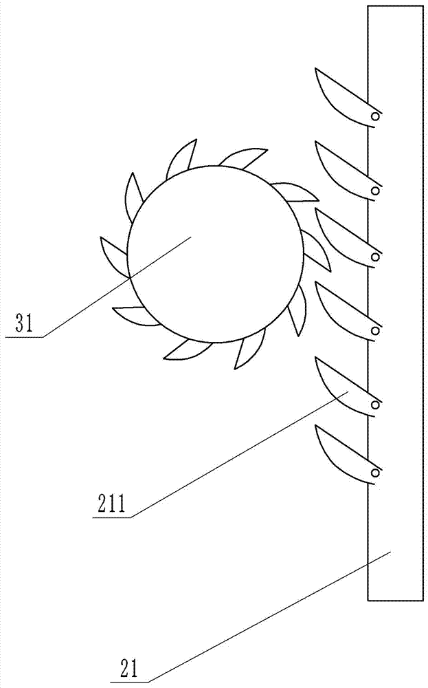
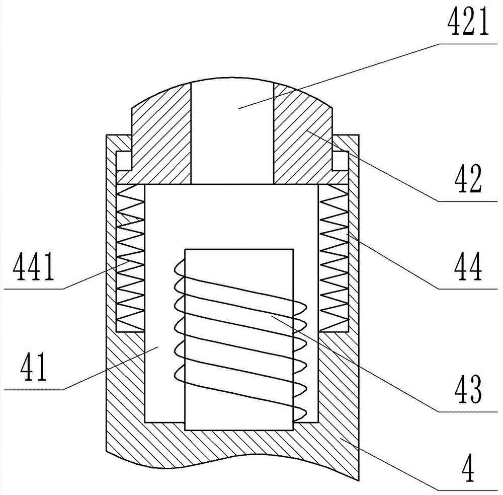
[0023] The reference signs in the accompanying drawings include: lower template 1, frame 11, guide post 12, upper template 2, transmission rod 21, pawl 211, elastic plate 22, punch 23, spring 24, rotating shaft 3, ratchet 31 , positioning plate 32, positioning pin 321, punching block 4, cavity 41, magnet bump 42, punching hole 421, coil 43, chute 44, extension spring 441, wheel spoke 5.

[0024] Such as figure 1 , figure 2 As shown, the spoke air hole processing mold includes an upper mold and a lower mold for installing the spoke 5, the upper mold is installed on the punching machine, and moves up and down as the punching machine works. The upper mold includes an upper template 2, a punch 23 and a transmission rod 21, and the side wall of the punch 23 is provided with an electromagnet; Lower movable stopper, so this ratchet 211 can only swing upwards. Both the punch...


PUM


Abstract

The invention belongs to the technical field of punching machining and particularly discloses a spoke air hole machining die. The spoke air hole machining die comprises an upper die and a lower die. The upper die comprises an upper die plate, a transmission rod and a punch. Pawls are hinged to the transmission rod. The lower die comprises a lower die plate, a rack, a rotating shaft and a punching block. The rotating shaft is rotationally connected to the rack, and the rotating shaft is in interference fit with the rack. A positioning plate and a ratchet wheel are fixed to the rotating shaft. A through hole matched with a spoke bolt hole is formed in the positioning plate. A cavity and a sliding groove communicating with the cavity are formed in the upper portion of the punching block. A magnet protruding block is connected to the sliding groove in a sliding manner, a punching hole is formed in the magnet protruding block, and a coil located below the magnet protruding block is arranged in the punching block. A controller and a speed sensor are installed on the rack, and the speed sensor and the coil are electrically connected with the controller. The spoke air hole machining die is adopted for machining a spoke air hole, after hole punching is completed, a spoke can be driven to rotate, punching continuity is ensured, and in addition, friction between the spoke and the magnet protruding block in the spoke rotating process can be avoided.

Description

technical field [0001] The invention belongs to the technical field of stamping processing, in particular to a mold for processing spoke air holes. Background technique [0002] At present, the most widely used wheels on automobiles are steel wheels, which generally consist of two parts, the rim and the spokes, which are manufactured separately and then assembled and welded together. Among them: the geometric structure of the spoke is composed of the installation plane, the transition curve section and the direct section, and the middle hole and the bolt hole are processed on the installation plane, and the installation plane is fixed with the car hub by bolts; the straight section is welded together with the rim ; The transition curve section plays the role of connecting the installation plane and the straight section, and the transition curve section is processed with air holes. With the rapid development of the automobile industry, the product quality of the spokes has a...

Claims


Application Information

Patent Timeline
Patent Type & Authority Applications(China)
IPC IPC(8): B21D28/34B21D53/26
CPCB21D28/34B21D53/265
Inventor 刘文
Owner 重庆鼎汉巅宏汽车零部件有限公司
Why Eureka
Try Eureka