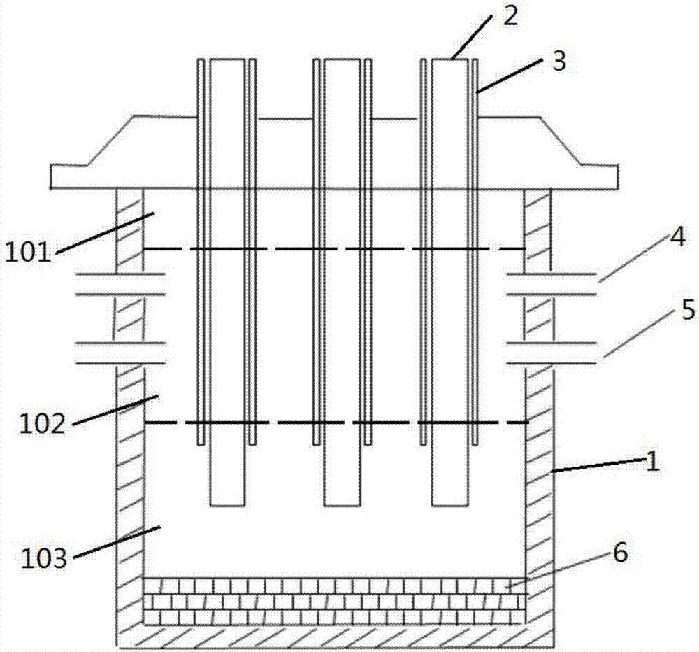
Calcium carbide furnace

A calcium carbide furnace and furnace body technology, applied in the directions of magnesium oxide, carbide, calcium carbide, etc., can solve the problems of difficulty in the furnace, sticky calcium carbide, affecting normal production, etc., so as to reduce the power consumption of calcium carbide production, increase the temperature of raw materials, avoid The effect of agglomeration

Pending Publication Date: 2017-07-21
SHENWU ENVIRONMENTAL TECH CO LTD
View PDF10 Cites 4 Cited by
  • Summary
  • Abstract
  • Description
  • Claims
  • Application Information

AI Technical Summary

Problems solved by technology

There is also a part of magnesium oxide that reacts with nitrogen in the melting zone to form magnesium nitride (Mg 3 N 2 ), making calcium carbide sticky, making it difficult to bake and affecting normal production

Method used


Image

  • Calcium carbide furnace

Examples


Embodiment 1

[0034] 1. The spherical material is sent into the calcium carbide furnace through the feeding pipe, and the components of the spherical material are semi-coke and lime.

[0035] 2. Feed oxygen into the furnace through the oxygen-containing gas inlet.

[0036] 3. Heating the spherical material to about 2000°C, the carbon in the spherical material and the CO in the gas will reduce the magnesium oxide in it to generate calcium carbide and tail gas containing magnesium vapor; part of the carbon and oxygen in the spherical material will be incompletely combusted, Provide part of the energy for calcium carbide production.

[0037] 4. The tail gas containing magnesium vapor rises, and the temperature gradually decreases. In the thermosphere zone of 1400-1600 ° C, it is discharged from the calcium carbide furnace through the tail gas outlet.

[0038] 5. The tail gas containing magnesium vapor enters the flue from the tail gas outlet, and when the temperature drops below 1200°C in the...

Embodiment 2

[0041] 1. The spherical material is sent into the calcium carbide furnace through the feeding pipe, and the components of the spherical material are biomass and lime.

[0042] 2. Feed oxygen into the furnace through the oxygen-containing gas inlet.

[0043] 3. Heating the spherical material to about 2100°C, the carbon in the spherical material and the CO in the gas will reduce the magnesium oxide in it to generate calcium carbide and tail gas containing magnesium vapor; part of the carbon and oxygen in the spherical material will be incompletely combusted, Provide part of the energy for calcium carbide production.

[0044] 4. The tail gas containing magnesium vapor rises, and the temperature gradually decreases. In the thermosphere zone of 1400-1600 ° C, it is discharged from the calcium carbide furnace through the tail gas outlet.

[0045] 5. The tail gas containing magnesium vapor enters the flue from the tail gas outlet, and when the temperature drops below 1200°C in the flu...


PUM


Abstract

The invention discloses a calcium carbide furnace which comprises a furnace body, an electrode, a feeding pipe, a tail gas outlet and an oxygen-containing gas inlet. The electrode and the feeding pipe are embedded at the top of the furnace body and extend into a cavity of the furnace body, the cavity of the furnace body is divided into a material layer area, a heat layer area and a reaction area sequentially from top to bottom, and temperature of the heat layer area is 1400-1600 DEG C when the calcium carbide furnace works; the tail gas outlet is arranged on the side wall of the heat layer area of the furnace body, and the oxygen-containing gas inlet is arranged on the side wall of the furnace body and positioned below the tail gas outlet. By arranging the tail gas outlet in the heat layer area, magnesium steam in tail gas is ensured not to be in oxidizing reaction with CO; by arranging the oxygen-containing gas inlet below the tail gas outlet, part of carbon in raw materials is combusted, so that energy consumption during calcium carbide production is lowered.

Description

technical field [0001] The invention belongs to the technical field of calcium carbide production equipment, in particular to a high-efficiency calcium carbide furnace. Background technique [0002] Calcium carbide is an important chemical raw material, and its main component is calcium carbide. In recent years, with the continuous development of economy and society, the industrial demand for calcium carbide is increasing. [0003] At present, the method of industrially producing calcium carbide is mainly electrothermal method. It first mixes the lime and coke that meet the requirements of calcium carbide production according to the specified ratio, and then uses the bucket elevator to send the furnace charge to the top silo of the calcium carbide furnace, and feeds the charge into the electric furnace through the material pipe, and the charge passes through the electric furnace. The electric resistance heat reaction between the electrode arc pad and the furnace charge pro...

Claims


Application Information

Patent Timeline
IPC IPC(8): C01B32/942C01F5/04
CPCC01F5/04
Inventor 张顺利丁力贾懿曼董宾郭启海吴道洪
Owner SHENWU ENVIRONMENTAL TECH CO LTD
Why Eureka
Try Eureka