

Turbofan shaped graded drop type vertical shaft
A drop-type, vertical shaft technology, applied in the direction of drainage, sewage removal, drainage structures, etc., can solve the adverse effects on the safe and stable operation of the deep tunnel system, the unfavorable smooth transition of the water flow in the bottom regulation and storage tunnel, and the reduction of the effective flow area of the discharged water flow, etc. , to achieve the effect of suppressing the influence of centrifugal force, lengthening the outflow width and high space utilization
- Summary
- Abstract
- Description
- Claims
- Application Information
AI Technical Summary
Problems solved by technology
Method used
Image

Examples
Embodiment 1
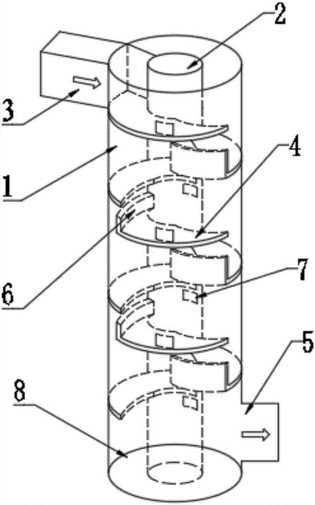
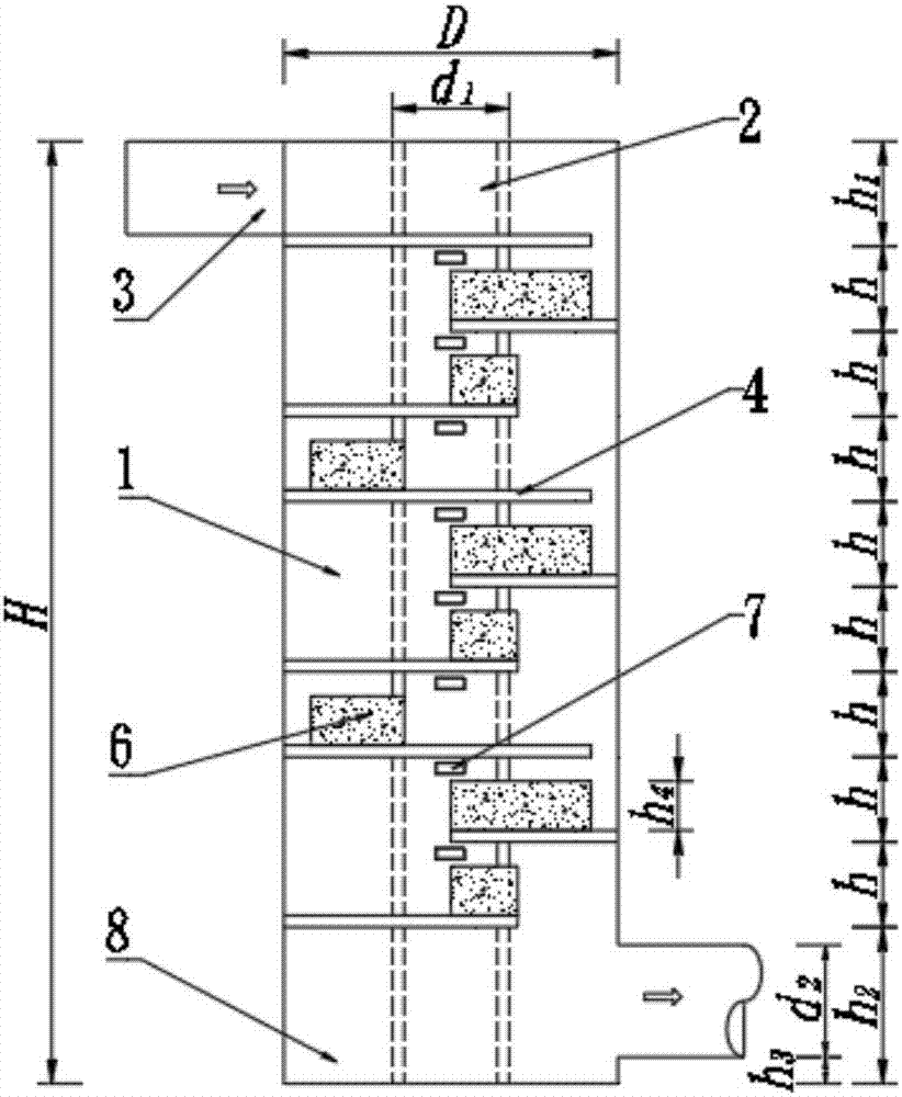
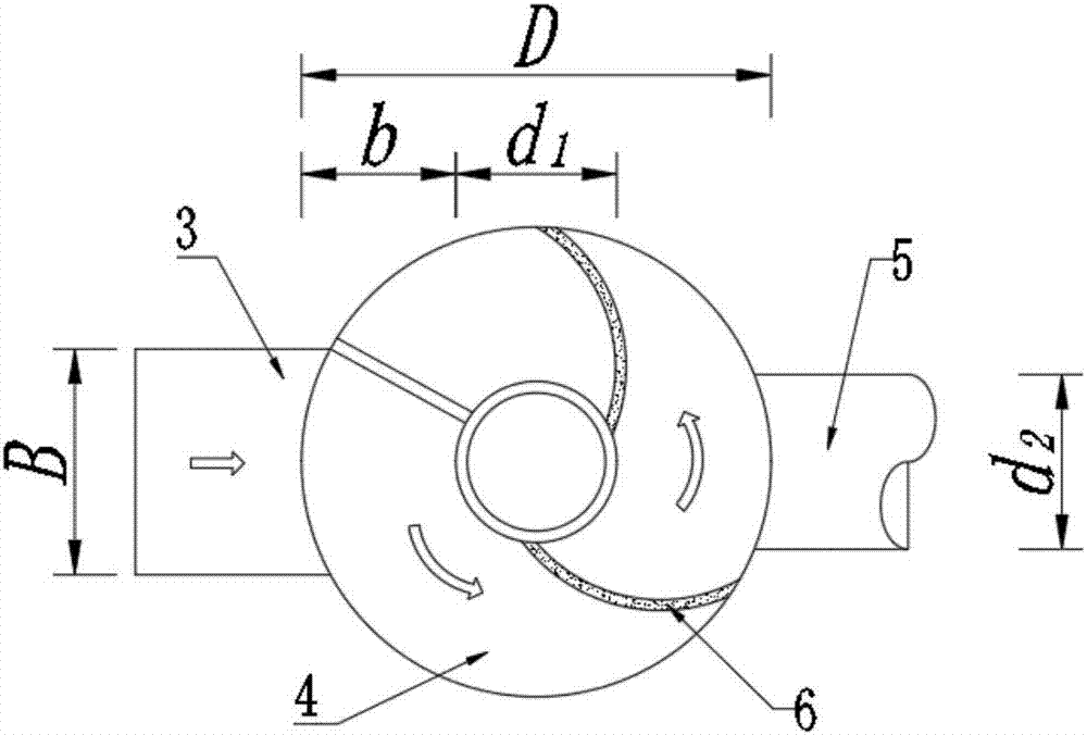
[0032] The structural layout of the turbo fan-shaped grading drop shaft in embodiment 1 is as follows figure 1 , figure 2 , image 3 , Figure 4 and Figure 5 As shown, the graded drop-type swirl shaft includes a shaft 1, an exhaust pipe 2, an inlet channel 3, a swirl plate 4, a storage tunnel entrance 5, a water retaining plate 6, a ventilation hole 7 and a water cushion 8. Wherein the number of swirl plates 4 is 9. The water inlet channel 3 is connected to the swirl plate 4 on the first floor, and the tail end of each swirl plate 4 is connected to the head end of the next swirl plate 4 on the horizontal projection plane, forming a circular area Graded rotary water flow channel. The swirl plate 4 is a plate of equal thickness, the elevation of the inner and outer bottoms is equal, and the flow edge of the swirl plate 4 is a curved arc at the front side. The head end of the swirl plate 4 is vertically provided with a water retaining plate 6 , and the height of the water...
Embodiment 2
[0036] The structural layout of the scroll fan-shaped grading drop-type shaft in embodiment 2 is as follows figure 1 , figure 2 , image 3 , Figure 4 , Figure 5 and Figure 6 As shown, the graded drop-type swirl shaft includes a shaft 1, an exhaust pipe 2, an inlet channel 3, a swirl plate 4, a storage tunnel entrance 5, a water retaining plate 6, a ventilation hole 7 and a water cushion 8. Wherein the number of swirl plates 4 is 9. The water inlet channel 3 is connected to the swirl plate 4 on the first floor, and the tail end of each swirl plate 4 is connected to the head end of the next swirl plate 4 on the horizontal projection plane, forming a circular area Graded rotary water flow channel. The swirl plate 4 is a unequal-thick plate with an arc-shaped upper surface, the elevation of the outer bottom is higher than that of the inner bottom, and the outlet edge of the swirl plate 4 is a curved front-side arc. The head end of the swirl plate 4 is vertically provide...
PUM
 Abstract
Description
Claims
Application Information