Water-rich stratum tunnel bottom drainage structure and construction method thereof

A technology of water-rich strata and drainage structure, applied in the directions of drainage, separation method, water/sewage treatment, etc., can solve the problems of difficult maintenance and management, the inability to effectively drain the accumulated water, and the drainage of water at the bottom of the tunnel. The effect of dredging work, improving the drainage capacity of the tunnel, and increasing the cross-sectional area of ​​the water

Active Publication Date: 2017-07-21
SOUTHWEST JIAOTONG UNIV
View PDF19 Cites 21 Cited by
  • Summary
  • Abstract
  • Description
  • Claims
  • Application Information

AI Technical Summary

Problems solved by technology

Since the central drainage ditch is set inside the tunnel, the water at the bottom of the tunnel cannot be discharged; in addition, the bottom of the tunnel (referred to as the tunnel bottom) in the existing drainage system mainly includes: the surrounding rock at the bottom, the initial support of the inverted arch, and the secondary concrete lining of the inverted arch. , inverted arch filling, pavement structure, roadside ditch, deep buried ditch, curb stone, cable trough, etc.
Due to the lack of an effective drainage system at the bottom of the tunnel, the internal drainage cannot discharge the water at the bottom of the tunnel, resulting in the inability to effectively drain the accumulated water below the inverted arch of the tunnel, causing the inverted arch to bear part of the water pressure, resulting in uplift of the inverted arch, deformation of the ballast bed, and cracks in the lining Water hazards such as damage to the ballast bed, slurry and mud flow, etc., maintenance and treatment are extremely difficult

Method used


Image

  • Water-rich stratum tunnel bottom drainage structure and construction method thereof
  • Water-rich stratum tunnel bottom drainage structure and construction method thereof
  • Water-rich stratum tunnel bottom drainage structure and construction method thereof

Examples


Embodiment 1

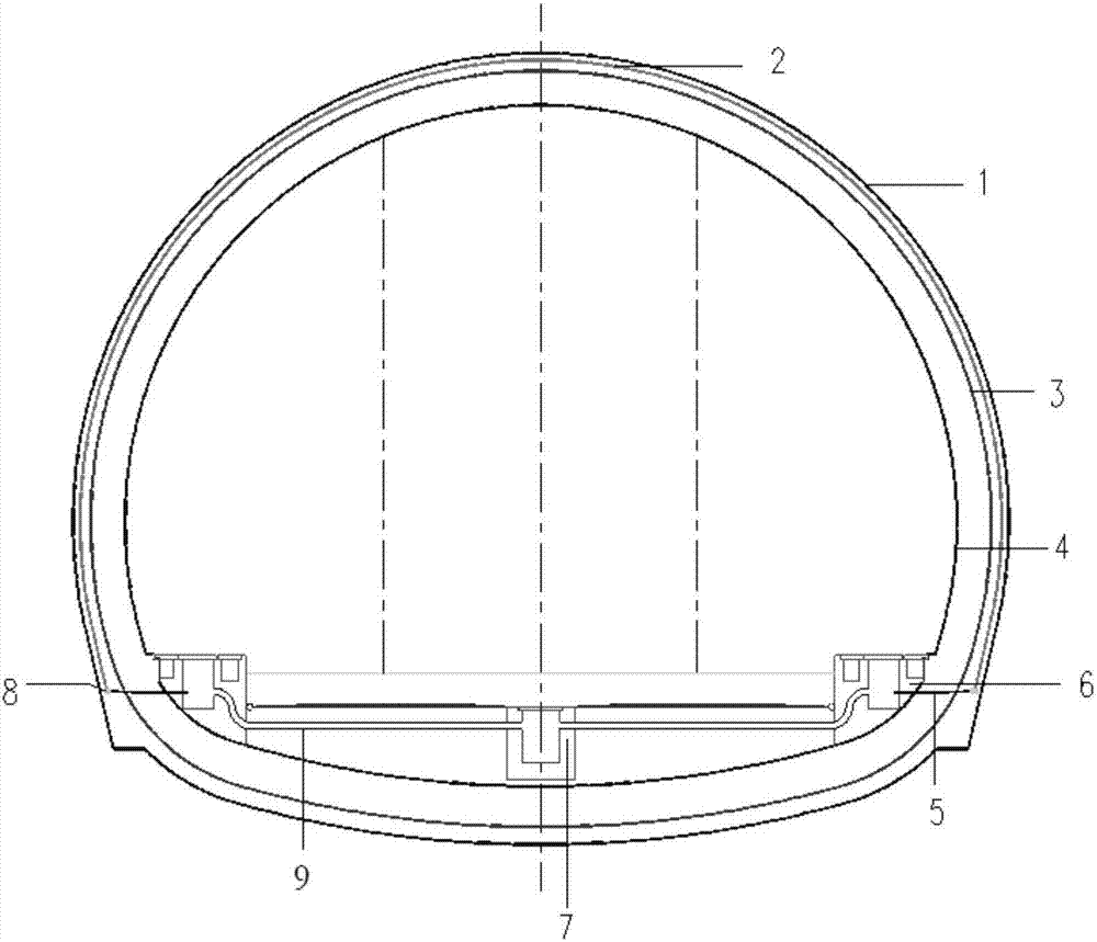
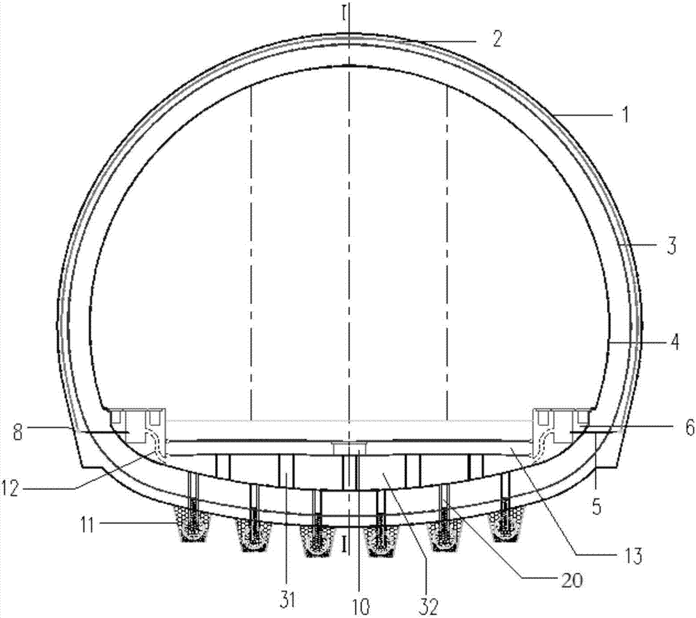
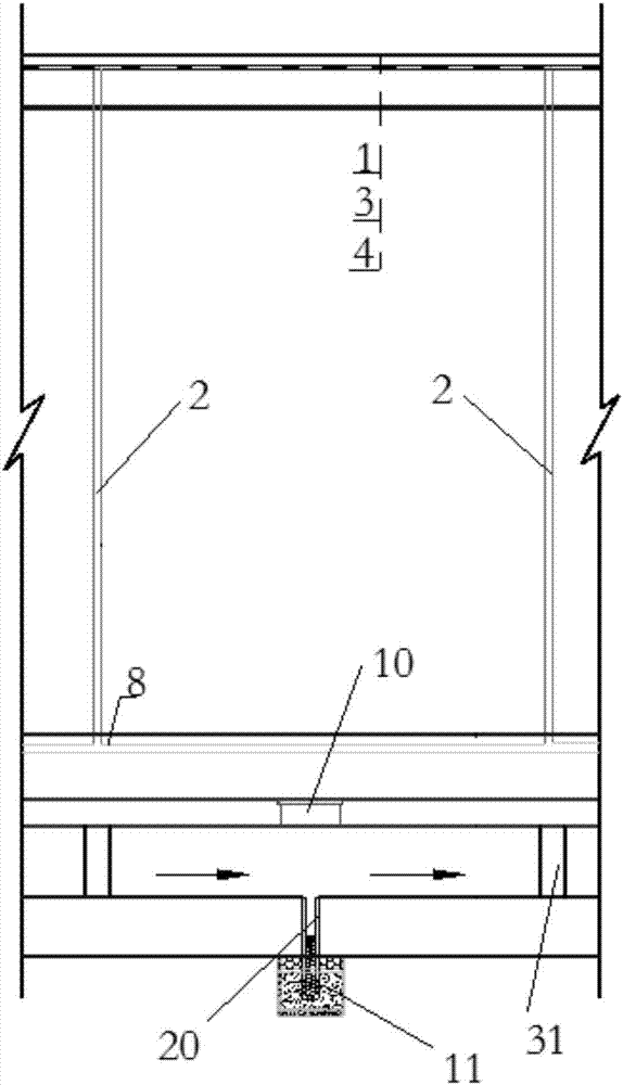
[0043] Such as figure 2 As shown, the drainage structure at the bottom of the tunnel in water-rich strata disclosed by the present invention includes an inverted arch and drainage side ditches 6 on both sides of the tunnel, and a ballast bed floor 13 is arranged above the inverted arch, and a load-carrying structure is arranged between the ballast bed floor 13 and the inverted arch. A culvert 32 at the bottom of the tunnel is formed between the pile 31, the bottom plate of the ballast bed 13 and the invert. The drainage side ditch 6 is connected to the water culvert 32 through the side ditch drain pipe 12, and a plurality of side ditch drain pipes 12 are arranged at intervals.

[0044] In order to facilitate the inspection, maintenance and dredging of the culvert 32 at the bottom of the tunnel, inspection wells 10 are arranged at intervals along the longitudinal direction of the tunnel in the center of the ballast bed floor 13 , and the inspection wells 10 lead to the culvert 32...

Embodiment 2

[0049] The difference between this embodiment and embodiment 1 is: as figure 2 , 3 As shown, in order to facilitate the discharge of accumulated water below the inverted arch at the same time, a water collection well 20 is arranged on the bottom surface of the water culvert 32. The lower end of the water collection well 20 passes through the inverted arch and extends to below the inverted arch. The bottom and side walls of the water collection well 20 are provided with The drain hole 18 is located below the inverted arch, the outside of the drain hole 18 is provided with a filter layer, and the water collection well 20 is provided with a one-way drainage device.

[0050] Such as Figure 5 As shown, the one-way drainage device includes a movable cover device 21 and a tension spring, and the movable cover device 21 includes a cover plate 28, a cover plate supporting member 29 and a hinge shaft 30, and one side of the cover plate 28 is connected with the hinge shaft 30. The wa...

Embodiment 3

[0056] The difference between this embodiment and embodiment 2 is: as figure 2 , 3 , 4, and 5, the water collection well 20 passes through the filter water collection device 11, the filter water collection device 11 is located below the inverted arch, the filter water collection device 11 includes a water collection pipe 15, and the water collection pipe 15 side walls are provided with water inlets 16 at intervals , The lower end of the water collection well 20 stretches into the water collection pipe 15, and the water discharge hole 18 communicates with the water collection pipe 15 inside. Wherein, the filter layer on the outside of the drain hole 18 includes the second filter layer 26 and the first filter layer 17 arranged from the inside to the outside, as preferably, the first filter layer 17 is a coarse sand filter layer, and the second filter layer 26 is For the fine sand filter layer, preferably, a stainless steel screen layer 27 is also provided between the drain hol...


PUM


Abstract

The invention relates to a water-rich stratum tunnel bottom drainage structure and a construction method thereof. A ballast bed base plate is arranged above an inverted arch in a spaced mode; bearing piles are arranged between the ballast bed base plate and the inverted arch; water passing culverts of the tunnel bottom are formed between the ballast bed base plate and the inverted arch; drainage side ditches communicate with the water passing culverts through side ditch drainage pipes; water collecting wells are arranged on the bottom faces of the water passing culverts; the lower ends of the water collecting wells penetrate through the inverted arch to extend into filtering water collecting devices under the inverted arch; water releasing holes are formed in the bottoms and the side walls of the water collecting wells, and filtering layers are arranged on the outer sides of the water releasing holes; and one-way drainage devices are arranged in the water collecting wells. An inverted arch filling part in the prior art is replaced with the ballast bed base plate and the bearing piles; on the basis of guaranteeing tunnel structure safety, the water passing cross section area of a tunnel drainage system is increased, and the tunnel drainage capacity is improved; and meanwhile, underground water under the water-rich stratum tunnel inverted arch is drained, tunnel bottom water pressure is reduced, and preventing of damage such as upheaval of the tunnel inverted arch and frost boiling and mud pumping of a ballast bed is facilitated.

Description

technical field [0001] The invention relates to the technical field of tunnel drainage facilities, in particular to a tunnel bottom drainage structure in a water-rich stratum and a construction method thereof. Background technique [0002] In recent years, with the large-scale construction of transportation infrastructure, many long and complex water-rich tunnels are being built or have been built. The existing tunnel drainage design is based on the conventional tunnel drainage design. The water around the tunnel structure permeates through the initial support and is drained to the central drainage ditch in the tunnel structure through the drainage blind pipe, and finally discharged out of the tunnel. Specifically, such as figure 1 As shown, the groundwater penetrates into the circular drainage blind pipe (serial number 2) through the initial support (serial number 1), and the circumferential drainage blind pipe (serial number 2) is laid along the circumference of the hole ...

Claims


Application Information

Patent Timeline
Patent Type & Authority Applications(China)
IPC IPC(8): E21F16/02E21D11/10C02F1/00B01D36/02
CPCB01D36/02E21D11/10E21F16/02C02F1/001
Inventor 张志强郑余朝陶伟明朱勇郑伟卿伟宸殷召念胡端张磊熊国兴
Owner SOUTHWEST JIAOTONG UNIV
Why Eureka
Try Eureka