Axial flow fan

An axial-flow fan and axial-flow wind technology, applied in mechanical equipment, machines/engines, liquid fuel engines, etc., can solve problems such as reducing the noise level of household appliances, reduce working speed and noise, increase air supply air volume, and improve performance. Effect

Inactive Publication Date: 2017-07-21
MIDEA GRP CO LTD
View PDF5 Cites 33 Cited by
  • Summary
  • Abstract
  • Description
  • Claims
  • Application Information

AI Technical Summary

Problems solved by technology

With the development of advanced fluid technology and software and hardware science and technology, fan/fan design optimization to obtain the best air volume and reduce noise has become a common technology, but the industry's pursuit of miniaturization and large air volume of fans has never been end
At present, ...

Method used


Image

  • Axial flow fan
  • Axial flow fan
  • Axial flow fan

Examples


Embodiment 1

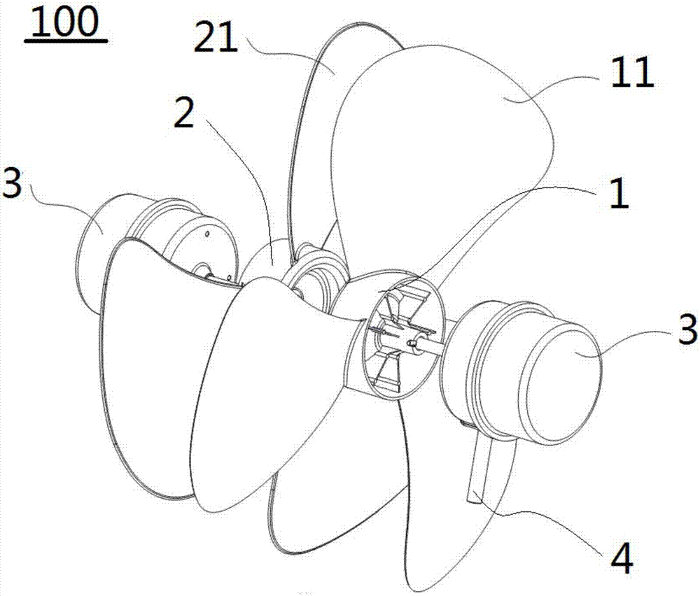
[0049] Such as figure 1 As shown, the axial flow fan 100 of the present invention mainly includes a first axial flow wind wheel 1, a second axial flow wind wheel 2 and two drive motors 3, and the two drive motors 3 are respectively connected to other structures such as a housing through a bracket 4 Connected, the first axial flow wind wheel 1 and the second axial flow wind wheel 2 are located between two drive motors 3 . The first fan blade 11 is arranged on the first axial flow wind wheel 1, and the second fan blade 21 is arranged on the second axial flow wind wheel 2. The first fan blade 11 utilizes a shaft end nut and a pin and a drive motor 3 close to it. The rotation direction is clockwise. The second fan blade 21 is connected and fixed with the drive motor 3 close to it by using the shaft end nut and pin. The rotation direction is counterclockwise. The bending direction of the first fan blade 11 is Opposite to the bending direction of the second blade 21, in the axial d...

Embodiment 2

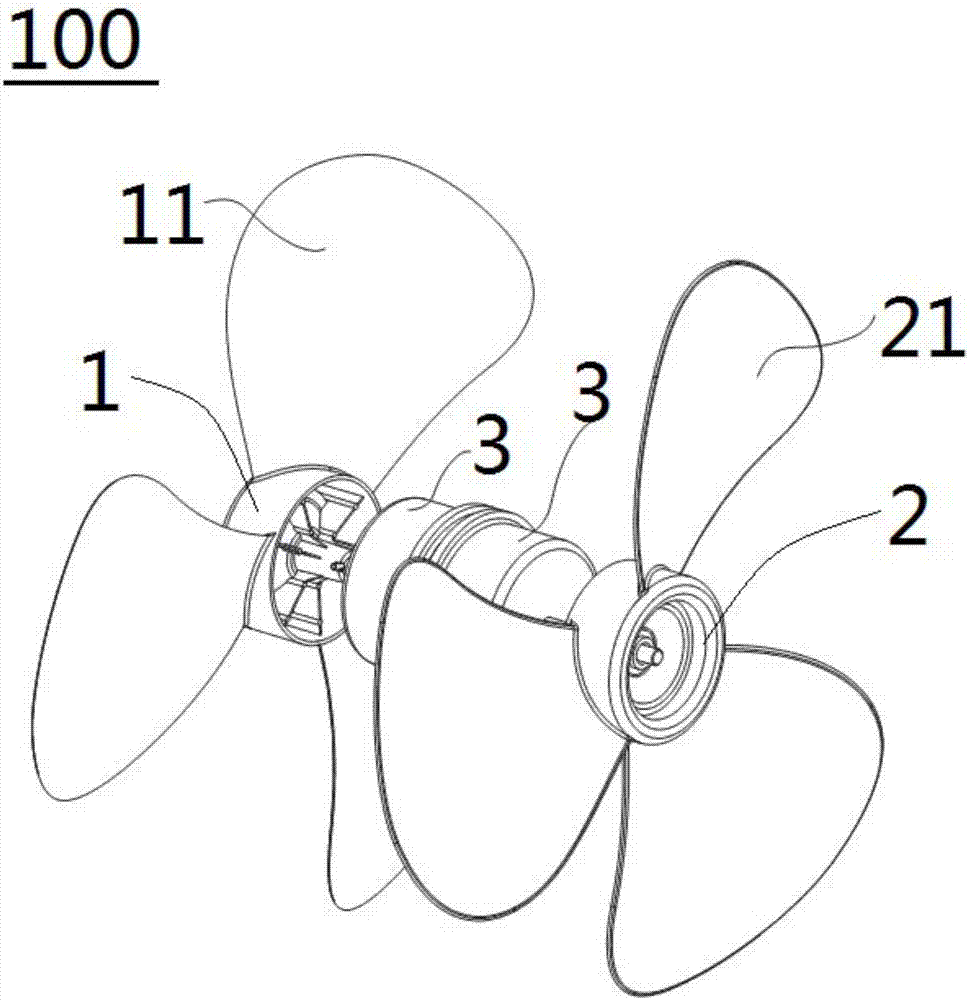
[0054] Such as figure 2 As shown, the structure of this embodiment is substantially the same as that of Embodiment 1, wherein the same components use the same reference numerals, the only difference is that the two driving motors 3 are located at the first axial flow wind wheel 1 and the second axial flow wind wheel between round 2.

Embodiment 3

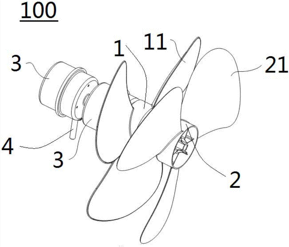
[0056] Such as image 3 As shown, the structure of this embodiment is substantially the same as that of Embodiment 1, wherein the same components use the same reference numerals, the only difference is that the two driving motors 3 are located at the side of the first axial flow wind wheel 1 far away from the second axis One side of the wind wheel 2.


PUM


Abstract

The invention discloses an axial flow fan, comprising: a first axial flow wind wheel, on which a first fan blade is arranged; a second axial flow wind wheel, on which the second axial flow wind wheel is arranged on the first On the air outlet side of the axial flow rotor, the second axial flow rotor is provided with a second fan blade, the bending direction of the first fan blade is opposite to that of the second fan blade; and a driving assembly, the driving assembly is the same as the first The axial flow wind wheel and the second axial flow wind wheel are respectively connected to drive the first axial flow wind wheel and the second axial flow wind wheel to rotate, the first axial flow wind wheel rotates around the first direction, and the second axial flow wind wheel rotates around the first direction Rotate in two directions, the second direction is opposite to the first direction. According to the axial flow fan of the present invention, the operating speed and noise can be greatly reduced, or the air supply volume can be increased, or the geometric dimensions such as the diameter of the fan blade can be reduced, so as to improve the performance of the axial flow fan. At the same time, the reverse air supply can be effectively realized, and the two-way reversible fan can be realized.

Description

technical field [0001] The invention relates to the technical field of ventilation, in particular to an axial flow fan. Background technique [0002] At present, in the home appliance market at home and abroad, axial flow fans are widely used, such as air conditioners, refrigerators, electric fans, microwave ovens and other products. The air volume and noise are the main performance indicators of fans / fans, especially under certain conditions. The noise is low, and some scenes also require high wind speed and uniform distribution. The application of axial flow fans / fans in the home appliance market usually focuses on fan blades with a diameter of 70-900mm, a speed of 500-3000r / min, and an air volume of 40-1200m3 / h. It has always been the goal of the industry to reduce the size and noise while increasing the air volume. With the development of advanced fluid technology and software and hardware science and technology, fan / fan design optimization to obtain the best air volume...

Claims


Application Information

Patent Timeline
IPC IPC(8): F04D25/08F04D29/66F04D29/32F04D29/38
CPCF04D25/08F04D25/06F04D29/325F04D29/386F04D29/666
Inventor 李书奇张辉张冀喆明乐乐蓝渊
Owner MIDEA GRP CO LTD
Why Eureka
Try Eureka