Miniaturized high performance resonator and radio frequency band-pass filter

A resonator, high-performance technology, applied in the field of microwave radio frequency, can solve the problems of increasing the volume of the communication system, the system power consumption, the system manufacturing cost, the system volume, and the system loss, etc., to achieve compact size, reduce volume, and reduce power consumption. Effect

Inactive Publication Date: 2017-07-21
四川众为创通科技有限公司
View PDF4 Cites 0 Cited by
  • Summary
  • Abstract
  • Description
  • Claims
  • Application Information

AI Technical Summary

Problems solved by technology

[0004] The technical problem to be solved by the present invention is that the existing resonators need to increase the size in order to increase the resonance frequency, but increasing the size of the resonator will increase the volume of the entire communication system, the power consumption of the system and the manufacturing cost of the system; at the same time , the traditional filter will also increase the loss of the system and increase the volume of the entire system, while the elliptic function filter has a complex structure and is not easy to implement. The purpose is to provide a miniaturized high-performance resonator and a radio frequency bandpass filter to solve above question

Method used


Image

  • Miniaturized high performance resonator and radio frequency band-pass filter
  • Miniaturized high performance resonator and radio frequency band-pass filter
  • Miniaturized high performance resonator and radio frequency band-pass filter

Examples


Embodiment 1

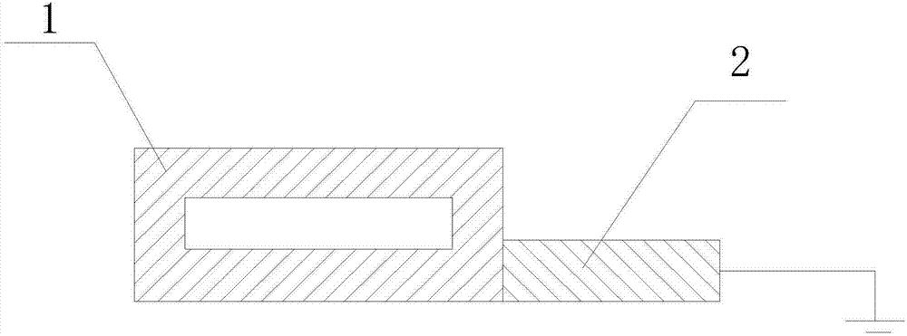
[0046] Such as figure 1 , figure 2 and Figure 5 As shown, a miniaturized high-performance resonator of the present invention includes a low-impedance section 1 and a high-impedance section 2; one end of the high-impedance section 2 is connected to the low-impedance section 1, and the other end is grounded; the low-impedance section 1 includes a microstrip line, the microstrip line is closed into a ring; the length of the closed microstrip line is preferably 17.4mm, the minimum distance between the inner rings of the closed microstrip line is preferably 0.1mm, and the closed ring-shaped The width of the microstrip line is preferably 0.45mm. The length of the high impedance section 2 is preferably 17.85 mm, and the width of the high impedance section 2 is 0.1 mm.

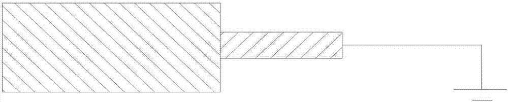
[0047] When this embodiment is implemented, figure 1 For the resonator of this embodiment, figure 2 It is an existing resonator with the same size as the present embodiment, Figure 5 Based on the simulation ...

Embodiment 2

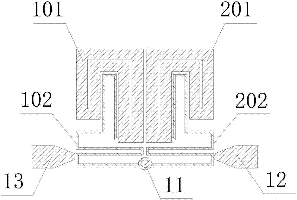
[0049] Such as image 3 and Figure 6 As shown, this embodiment includes a resonator, a feeder and a ground hole 11; the feeder is connected to the high impedance section of the resonator; the end of the high impedance section of the resonator away from the low impedance section is connected to the ground hole 11. The resonator includes a first resonator and a second resonator; the first resonator includes a first low impedance section 101 and a first high impedance section 102; the second resonator includes a second low impedance section 201 and The second high-impedance section 202; the feeder includes the first feeder 13 and the second feeder 12; the first low-impedance section 101 is adjacent to the second low-impedance section 201; the first high-impedance section 102 is far away from the first One end of a low-impedance section 101 is connected to the ground hole 11; the second high-impedance section 202 is connected to the ground hole 11 at an end far away from the sec...

Embodiment 3

[0053] Such as image 3 , Figure 7 and Figure 8 As shown, in this embodiment, on the basis of Embodiment 2, the radius of the ground hole 11 is defined as R, and the distance between the first low-impedance section 101 and the second low-impedance section 201 is defined as S.

[0054] When this embodiment is implemented, Figure 7 It is the change curve of the response curve of the filter with R. It can be seen that the positions of TZ1 and TZ2 can be adjusted by adjusting R, so it is suitable for filtering in various frequency bands; Figure 8 It is the change curve of the response curve of the filter with S. It can be seen that the positions of TZ1 and TZ2 can also be adjusted by adjusting S, so it is suitable for filtering in various frequency bands. Compared with the existing filters, the adjustment is more convenient.


PUM

PropertyMeasurementUnit
Widthaaaaaaaaaa
Lengthaaaaaaaaaa
Widthaaaaaaaaaa

Abstract

The invention discloses a miniaturized high performance resonator comprising a low impedance section and a high impedance section. One end of the high impedance section is connected with the low impedance section, and the other end is grounded. The low impedance section comprises a microstrip line which is closed into a loop. The invention also discloses a radio frequency filter using the miniaturized high performance resonator. The radio frequency filter comprises the resonator, a feeder line and a grounding hole. The feeder line is connected with the high impedance section of the resonator. One end, which is away from the low impedance section, of the high impedance section of the resonator is connected with the grounding hole. The loop microstrip line is arranged at the low impedance section so that the size is enabled to be less than that of the conventional resonator under the same resonant frequency, the volume of the whole communication system can be reduced, and the power consumption of the system and the manufacturing cost of the system can be reduced. Meanwhile, the loop resonator can be more flexible in design and processing because of no clad copper in the low impedance line, and thus a novel multistage resonant cascade structure can be accordingly designed.

Description

technical field [0001] The invention relates to the field of microwave radio frequency, in particular to a miniaturized high-performance resonator and a radio frequency bandpass filter. Background technique [0002] With the rapid development of electronic information, the increasingly tight spectrum resources are becoming more scarce. In order to improve the communication capacity and reduce the signal crosstalk between adjacent channels, higher requirements are put forward for the filter clutter suppression ability and selectivity. In order to improve the out-of-band rejection and frequency selectivity of the filter, traditional Butterworth and Chebyshev filters are mainly realized by increasing the number of resonators, but this will lead to an increase in circuit loss, volume and production cost. Although the elliptic function filter can achieve high out-of-band rejection and selectivity by introducing symmetrical transmission zeros in the stop band, it is difficult to r...

Claims


Application Information

Patent Timeline
IPC IPC(8): H01P7/08H01P1/203
CPCH01P7/08H01P1/203
Inventor 刘宗岳
Owner 四川众为创通科技有限公司
Why Eureka
Try Eureka