Rotor structure of magnetic levitation ultra high speed permanent magnet motor

A permanent magnet motor and rotor structure technology, applied in the direction of magnetic circuit shape/style/structure, magnetic circuit rotating parts, magnetic attraction or thrust holding device, etc., can solve the problem of weakening the effective magnetic field of permanent magnets and the bearing capacity of magnetic bearings Large size, high volume and weight, etc., to achieve the effect of increasing the critical speed of the first-order bending, increasing the linear speed, and reducing the weight of the rotor

Pending Publication Date: 2017-07-21
天津飞旋高速电机科技有限公司 +1
View PDF9 Cites 11 Cited by
  • Summary
  • Abstract
  • Description
  • Claims
  • Application Information

AI Technical Summary

Problems solved by technology

[0003] (1) The shaft is a solid structure, and non-magnetic materials must be used, such as non-magnetic stainless steel, to avoid short-circuiting of the magnetic field at the contact between the permanent magnet and the shaft. When the magnetic field is short-circuited, a huge magnetic flux leakage will occur, thus weakening the The effective magnetic field of the permanent magnet;
[0004] (2) The s

Method used


Image

  • Rotor structure of magnetic levitation ultra high speed permanent magnet motor
  • Rotor structure of magnetic levitation ultra high speed permanent magnet motor
  • Rotor structure of magnetic levitation ultra high speed permanent magnet motor

Examples


Embodiment 1

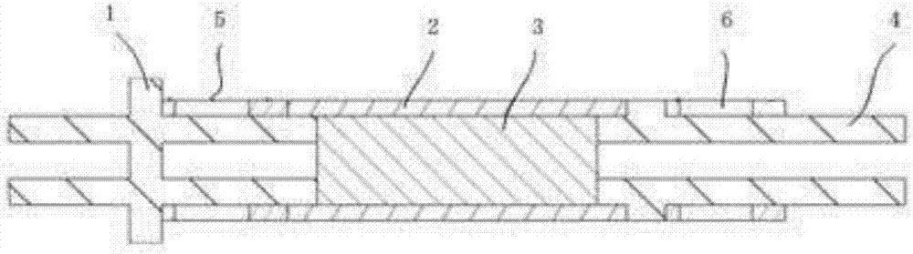
[0026] Such as figure 2 As shown, this embodiment discloses a rotor structure of a maglev ultra-high-speed permanent magnet motor, which is a classic three-section shaft structure as a whole. The thrust disc and the left shaft are combined into one, which is the thrust disc shaft 1, which is made of high yield strength magnetic metal material, and the corresponding part of the thrust disc must be a solid structure, which can reduce the maximum centrifugal stress by half, and the thrust disc shaft 1 The part in contact with the permanent magnet 3 must be a hollow structure, which can reduce the short-circuit effect on the magnetic field of the permanent magnet 3 . The rest of the thrust disc shaft 1 can be made into a hollow structure to reduce the weight of the shaft 4 . The first magnetic bearing assembly 5 of the radial magnetic bearing on the right side of the thrust disk shaft 1 is a ring structure, usually made of silicon steel sheets to reduce eddy current loss. The fi...

Embodiment 2

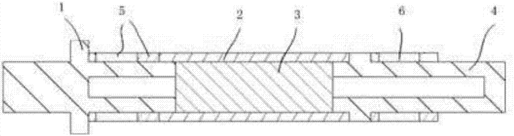
[0033] Such as image 3 As shown, this embodiment discloses a rotor structure of a maglev ultra-high-speed permanent magnet motor. The difference from Embodiment 1 is that the shaft 4 in this embodiment is made of magnetically conductive material, and the shaft 4 is in contact with the permanent magnet 3 The part of the permanent magnet 3 is a hollow structure, and the end away from the permanent magnet 3 adopts a closed structure. The shaft 4 is the shaft extension end, which needs to be connected with the load. In some practical occasions, it is better to use a solid shaft, and it can also have the advantages of a hollow structure to reduce the mass.

[0034] In addition, the sheath 2 is made of carbon fiber composite material, because the thermal expansion coefficient of carbon fiber composite material is basically 0, which cannot be assembled by heating, and can only be assembled by cooling.

Embodiment 3

[0036] Such as Figure 4 As shown, this embodiment discloses a rotor structure of a magnetic levitation ultra-high-speed permanent magnet motor. The difference from Embodiment 1 is that the shaft 4 in this embodiment is made of non-magnetic material, and its whole is a solid structure. The shaft 4 is made of non-magnetic material, which can make the magnetic flux leakage of the permanent magnet smaller.


PUM


Abstract

The invention relates to a rotor structure of a magnetic levitation ultra high speed permanent magnet motor. The rotor structure comprises a thrust disc shaft, a sheath, a permanent magnet, a shaft, a first magnetic bearing assembly and a second magnetic bearing assembly, wherein the thrust disc shaft comprises a left shaft and a thrust disc, the thrust disc is a solid structure, the portion of the thrust disc shaft contacting with the permanent magnet is a hollow structure, the permanent magnet is a cylindrical structure, and the thrust disc and the left shaft are integrated into body and are prepared from a magnetic conduction metal material with high yield strength. The position corresponding to the thrust disc is must a solid structure, the maximum centrifugation stress can be reduced by half, the portion of the thrust disc shaft contacting with the permanent magnet is must the hollow structure, so the short circuit effect on a permanent magnet magnetic field can be reduced; the other portion of the thrust disc shaft is made to be a hollow structure, so weight of the shaft is reduced; the thrust disc and the partial hollow shaft are the integrated structure, the maximum stress of the center of the thrust disc can be substantially reduced, rotor linear velocity and rotor dynamics characteristics of the magnetic levitation ultra high speed permanent magnet motor are improved, and bearing capability of the magnetic bearing is further reduced.

Description

technical field [0001] The invention relates to the technical field of magnetic levitation ultra-high speed, in particular to a rotor structure of a magnetic levitation ultra-high speed permanent magnet motor. Background technique [0002] The cross-sectional view of the mainstream structure of the current maglev ultra-high-speed permanent magnet motor is as follows: figure 1 As shown, its main disadvantages are: [0003] (1) The shaft is a solid structure, and non-magnetic materials must be used, such as non-magnetic stainless steel, to avoid short-circuiting of the magnetic field at the contact between the permanent magnet and the shaft. When the magnetic field is short-circuited, a huge magnetic flux leakage will occur, thus weakening the The effective magnetic field of the permanent magnet; [0004] (2) The shaft is a solid structure with heavy weight, which leads to excessive bearing capacity of the magnetic bearing and high volume and weight; [0005] (3) The thrust...

Claims


Application Information

Patent Timeline
IPC IPC(8): H02K1/22H02K1/28H02K7/09H02N15/00
CPCH02K1/22H02K1/28H02K7/09H02N15/00
Inventor 毕刘新邓仁杰衣富成项海铭洪申平
Owner 天津飞旋高速电机科技有限公司
Why Eureka
Try Eureka