
Equipment, system and method for observing unmanned aerial vehicle in third-party view angle

A technology for drones and equipment, which is applied to CCTV systems, components of TV systems, components of color TVs, etc., can solve the problem of not being able to view drones in real time, and achieve the effect of avoiding image instability.

Inactive Publication Date: 2017-07-21
高域(北京)智能科技研究院有限公司
View PDF6 Cites 4 Cited by
  • Summary
  • Abstract
  • Description
  • Claims
  • Application Information

AI Technical Summary

Problems solved by technology

[0007] In order to solve the technical problem in the prior art that the position information of the drone cannot be viewed in real time on the display screen of the drone or in the virtual device from other perspectives, the present invention provides a real-time view of the position information of the drone from a third perspective Apparatus, system and method for observing drones from a third-party perspective

Method used


Image

  • Equipment, system and method for observing unmanned aerial vehicle in third-party view angle
  • Equipment, system and method for observing unmanned aerial vehicle in third-party view angle
  • Equipment, system and method for observing unmanned aerial vehicle in third-party view angle

Examples


Embodiment 1

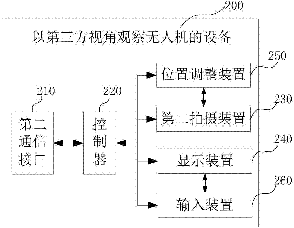
[0044] Such as figure 1 As shown, the present embodiment provides a system for observing drones from a third-party perspective, and the system includes:

[0045] The unmanned aerial vehicle 100, the preferred unmanned aerial vehicle 100 of this embodiment is a multi-rotor unmanned aerial vehicle, and the first photographing device 110, the positioning device 120 and the first communication interface 130 are arranged in the drone 100; the first photographing device 110 takes the unmanned aerial vehicle as the first-party perspective to observe and shoot; the positioning device 120 can be a GPS positioning chip or a Beidou system positioning chip, which is used to collect the current position information of the unmanned aerial vehicle 100; and the first shooting device 110 and the positioning device 120 The collected information is transmitted to the outside through the first communication interface 130, for example, to the remote controller for controlling the drone, the ground...

Embodiment 2

[0065] In this embodiment, on the basis of Embodiment 1, the automatic adjustment of the second camera 230 by the position adjustment device 250 is cancelled. position and / or angle adjustments. Other systems, equipment, and devices that are the same as those in Embodiment 1 will not be repeated here.

[0066]Preferably, the controller 220 selects whether to send the control signal of the display screen according to the user's own needs; when sending according to the user's own needs, the user can use the input device 260 (such as a button in the controller, or a touch screen in the display device, or the input button in the headset) the input needs to display the control signal to observe the drone from the perspective of a third party.

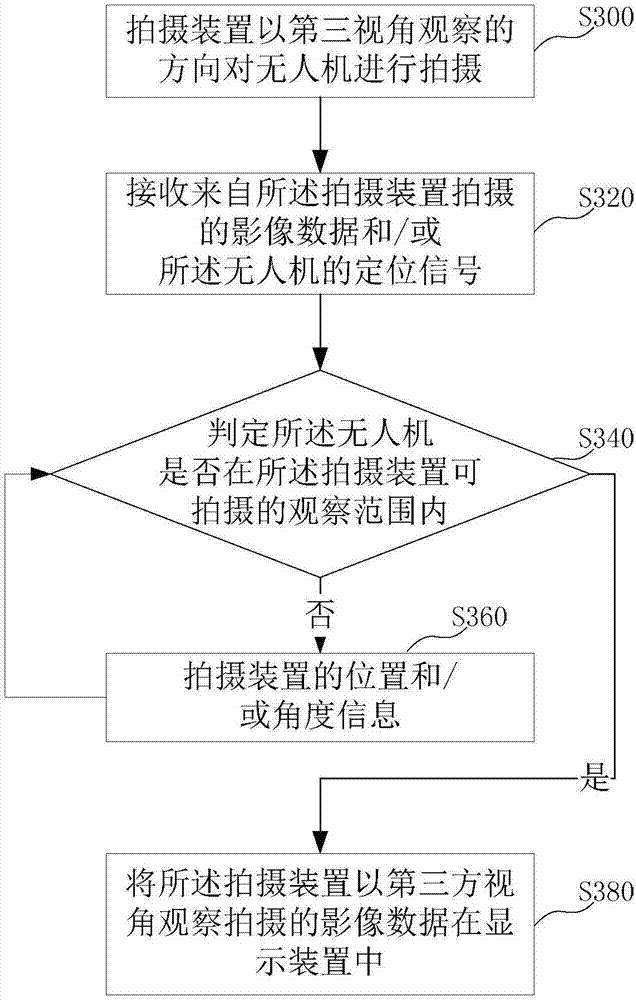
[0067] Such as Figure 4 As shown, the method for observing the drone from a third-party perspective provided by this embodiment includes:

[0068] S300. The photographing device photographs the object from a third-party perspective, speci...

Embodiment 3

[0082] In this embodiment, on the basis of Embodiment 1 and Embodiment 2, it is further preferred to install the camera on the head-mounted device, and the user can see the picture of observing the drone from a third-party perspective on the head-mounted device .

[0083] Preferably, in the case of selecting the above-mentioned "passive" adjustment of the second camera device, when it is observed from the head-mounted device that the drone is not within the observation range of the special camera device, a signal prompt is given in the user's field of view, Tell the user which direction to adjust the second camera (since the camera is set on the head-mounted device), so the user only needs to move his body or head to find the drone. Assume that the current user is using a head-mounted device to control the flight of the drone. After flying for 5 minutes, the user finds that he no longer knows where the current drone is, and then from the first-person perspective, he cannot obs...


PUM


Abstract

The invention belongs to the technical field of unmanned aerial vehicle applications, and provides equipment, a system and method capable of simultaneously checking unmanned aerial vehicle position information in a third view angle and observing the unmanned aerial vehicle in a third-party view angle. The equipment comprises a shooting device, a signal receiver, a controller, and a display device, wherein the shooting device is set to shoot the unmanned aerial vehicle in the third-party view angle; the signal receiver is connected with the shooting device and used for receiving image data shot by the shooting device; the signal receiver is further connected with the unmanned aerial vehicle through a wireless network so as to receive a positioning signal sent by a positioning device in the unmanned aerial vehicle; the controller is connected with the signal receiver and used for outputting a signal for judging whether the unmanned aerial vehicle is in a shootable observation range of the shooting device based on the positioning signal about the unmanned aerial vehicle received from the signal receiver and / or the own performance parameters of the shooting device; and the display device is used for receiving a control signal of the controller and photographing data transmitted by the signal receiver.

Description

technical field [0001] The present invention relates to the technical field of UAV application, in particular to a device, system and method for observing UAVs from a third-party perspective. Background technique [0002] With the advancement of electronic technology, especially the maturity of microelectronic control technology, flight technology is not limited to military applications; in recent years, consumer-grade unmanned aerial vehicles have been widely used in the field of aerial photography. For example, the solution of multi-rotor unmanned aerial vehicle can realize hovering in the air without operation, and due to the stable flight, increasingly mature control and low cost, this kind of multi-rotor unmanned aerial vehicle has begun to become a civil and consumer-grade The mainstream way of drones. And this kind of multi-rotor aircraft is often also equipped with a gimbal for stabilization, and a shooting device mounted on the gimbal; the video captured by the sho...

Claims


Application Information

Patent Timeline
Patent Type & Authority Applications(China)
IPC IPC(8): H04N7/18H04N5/232
CPCH04N7/18H04N23/66H04N23/617
Inventor 不公告发明人
Owner 高域(北京)智能科技研究院有限公司
Learn More