Hydraulic forming device with multipoint female groove, and method for manufacturing panel parts through using hydraulic forming device

A technology of hydraulic bulging and sheet metal, which is applied in the field of sheet processing equipment, hydroforming equipment, and sheet metal parts manufacturing. It can solve the problems of long manufacturing cycle, reduce flange parts, sheet metal blanks, and sheet damage, and save high costs. , Shorten the production cycle and improve production efficiency

Inactive Publication Date: 2017-07-25
GUANGXI UNIVERSITY OF TECHNOLOGY
View PDF7 Cites 3 Cited by
  • Summary
  • Abstract
  • Description
  • Claims
  • Application Information

AI Technical Summary

Problems solved by technology

[0002] Traditional sheet metal parts forming technology usually adopts stamping forming method. During the processing process, because the mold directly stamps the sheet, it is easy to cause damage to the sheet, thereby greatly reducing the forming quality of sheet metal parts; in addition, the huge noise generated by stamping will pollute the environment ; Hydroforming technology uses the lubricating contact between the fluid and the plate to improve the quality of the plate forming without generating noise pollution, so it is widely used; but with the development of the economy, sheet metal products tend to be diversified, small batches, The configuration is complicated, and the defects exposed by traditional hydroforming technology for diversified and flexible production are becoming more and more prominent:
[0003] On the one hand, in the process of producing sheet metal parts with different structural shapes, it is necessary to prepare molds of different configurations. Due to the long manufacturing cycle of the mold, the production cycle of the product is long, the production efficiency is low, and the production cost is high;
[0004] On the other hand, in the traditional hydroforming technology, pressure oil is used instead of the punch. In order to establish the pressure required for sheet metal forming, the flange part needs to provide a large blank-holding force for liquid sealing. However, a large blank-holding force The flow of the blank of the flange part will be blocked, which will reduce the effect of feeding the blank of the flange part to the middle, so that the pure expansion of the sheet will cause the middle part of the blank to become thinner or even cracked

Method used


Image

  • Hydraulic forming device with multipoint female groove, and method for manufacturing panel parts through using hydraulic forming device
  • Hydraulic forming device with multipoint female groove, and method for manufacturing panel parts through using hydraulic forming device
  • Hydraulic forming device with multipoint female groove, and method for manufacturing panel parts through using hydraulic forming device

Examples


Embodiment 1

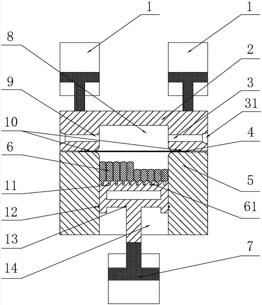
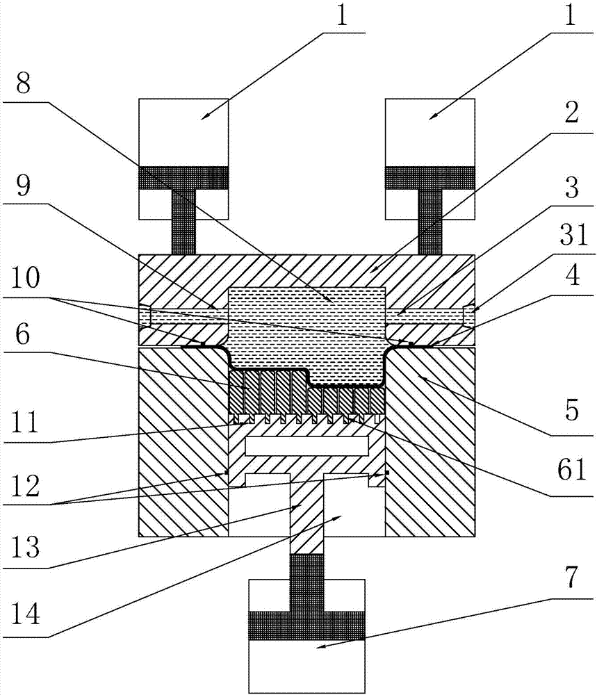
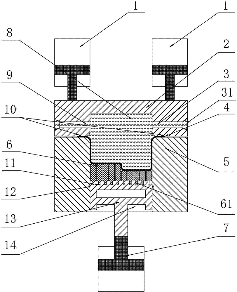
[0032] A sheet metal hydraulic bulging device with a multi-point die, comprising an upper mold 2 and a lower mold 5, the upper mold is connected to a blank holder cylinder 1, the lower mold is installed on a machine base, and the inner cavity of the lower mold is connected to the The cavity corresponding to the shape of the thin-walled deep-cavity plate part to be formed (that is, the cross-sectional shape of the cavity corresponds to the shape of the thin-walled deep-cavity plate part to be formed), and the upper mold is provided with a liquid chamber 8 corresponding to the cavity. The oil inlet channel 9 and the oil outlet channel 3 respectively located on both sides of the upper mold are connected, and the cross-sectional size of the bottom opening of the liquid chamber is consistent with the cross-sectional size of the cavity. When the upper and lower molds are closed, the opening of the liquid chamber is opposite to the cavity;

[0033] The bottom of the lower mold cavity ...

Embodiment 2

[0037] A method for making a deep-cavity plate part, the method is a method for making a thin-walled deep-cavity plate part using the plate hydraulic bulging device with a multi-point die described in Embodiment 1, comprising the following steps:

[0038] S1. Install the sheet blank: place the sheet blank 4 between the upper mold 2 and the lower mold 5, start the blank holder cylinder 1 to apply a blankholder force to the upper mold to clamp the sheet blank;

[0039]S2. Install the multi-point die: according to the shape of the bottom surface of the deep cavity plate parts, select small punches of different or the same height, and install them in the positioning holes of the back pressure die through arrangement and combination to form a thin-walled die with the required depth. Multi-point concave mold with consistent bottom surface shape of cavity plate parts;

[0040] S3. Connect the high-pressure oil circuit: the oil inlet channel is connected to the flange through the step...


PUM


Abstract

The invention relates to a hydraulic panel bulging device with a multipoint female groove. The hydraulic panel bulging device with the multipoint female groove comprises an upper mold and a lower mold, wherein the upper mold is provided with a liquid chamber corresponding to a cavity; a big through hole is formed in the middle of the lower mold; a back pressure mold connected with an ejecting cylinder is slidably arranged in the big through hole in a sealing way; positioning holes for installing small punches are formed in the upper surface of the back pressure mold; the small punches are uniformly distributed and tightly arranged; and the groove with the same shape as the bottom surface of a panel parts required to be manufactured is formed in the upper surfaces of the punches with same or different heights. A method for manufacturing a deep-cavity panel parts through using the hydraulic panel bulging device comprises the steps of S1, installing a panel blank; S2, installing the multipoint female groove; S3, exhausting and charging; S4, enabling the back pressure mold to close to the bottom surface of the panel blank; S5, carrying out initial contact molding; S6, drawing the mold for forming; S7, maintaining pressure; and S8, discharging oil and opening the mold. The bulging device can be applicable for producing panel pieces in different shapes without the need for replacing the mold, so that the cost is saved, the method is simple to operate and easy to control, the materials are saved, the efficiency is high, the occurrence of the phenomenon that the materials are cracked can be effectively avoided, and the bulging depth and the forming quality of the product are improved.

Description

technical field [0001] The invention belongs to the technical field of mechanical processing, and relates to a plate processing device and method, in particular to a hydroforming device with a multi-point die and a method for manufacturing plate parts with it. Background technique [0002] Traditional sheet metal parts forming technology usually adopts stamping forming method. During the processing process, because the mold directly stamps the sheet, it is easy to cause damage to the sheet, thereby greatly reducing the forming quality of sheet metal parts; in addition, the huge noise generated by stamping will pollute the environment ; Hydroforming technology uses the lubricating contact between the fluid and the plate to improve the quality of the plate forming without generating noise pollution, so it is widely used; but with the development of the economy, sheet metal products tend to be diversified, small batches, The configuration is complicated, and the defects exposed...

Claims


Application Information

Patent Timeline
Patent Type & Authority Applications(China)
IPC IPC(8): B21D26/031B21D26/021
CPCB21D26/031B21D26/021
Inventor 李健苏海迪吴量朱书建常雪
Owner GUANGXI UNIVERSITY OF TECHNOLOGY
Why Eureka
Try Eureka