Check patentability & draft patents in minutes with Patsnap Eureka AI!

Extruding-punching forging die for hub unit

A wheel hub unit and punching technology, which is applied in the direction of manufacturing tools, wheels, forging/pressing/hammer devices, etc., can solve the problems of long processing hours, high production costs, and low utilization rate of forging materials, so as to reduce the use of molds, Scientific structure and the effect of improving production efficiency

Inactive Publication Date: 2017-07-28
HUBEI TRI RING FORGING
View PDF5 Cites 7 Cited by
  • Summary
  • Abstract
  • Description
  • Claims
  • Application Information

AI Technical Summary

Problems solved by technology

[0003] This prior art has the following defects: 1. Since the length of the cylindrical end is about 80 mm to 120 mm, and the diameter of the through hole is about 50 mm to 70 mm, the processing time is long when drilling, reaming and boring, resulting in high production costs; 2. On the one hand, the metal material at the through hole is heated together with the blank before forging, and it also needs to flow and deform during forging, resulting in high energy consumption. This part of the material is removed as scrap during gold processing, and the utilization rate of forging materials is low.
[0004] In order to overcome the above defects, our company has improved the processing technology of the hub unit. By optimizing the forging structure, the hub unit is processed by extrusion and punching technology. First, a blind hole is formed by extrusion, and then the continuous skin is punched out through the punching die To form a through hole, this processing technology needs to be extruded first and then punched, requiring two sets of molds, which is inconvenient to process

Method used


Image

  • Extruding-punching forging die for hub unit
  • Extruding-punching forging die for hub unit
  • Extruding-punching forging die for hub unit

Examples


Embodiment Construction

[0025] The present invention will be described in further detail below in conjunction with the accompanying drawings and specific embodiments, and the implementation scope of the present invention is not limited thereto.

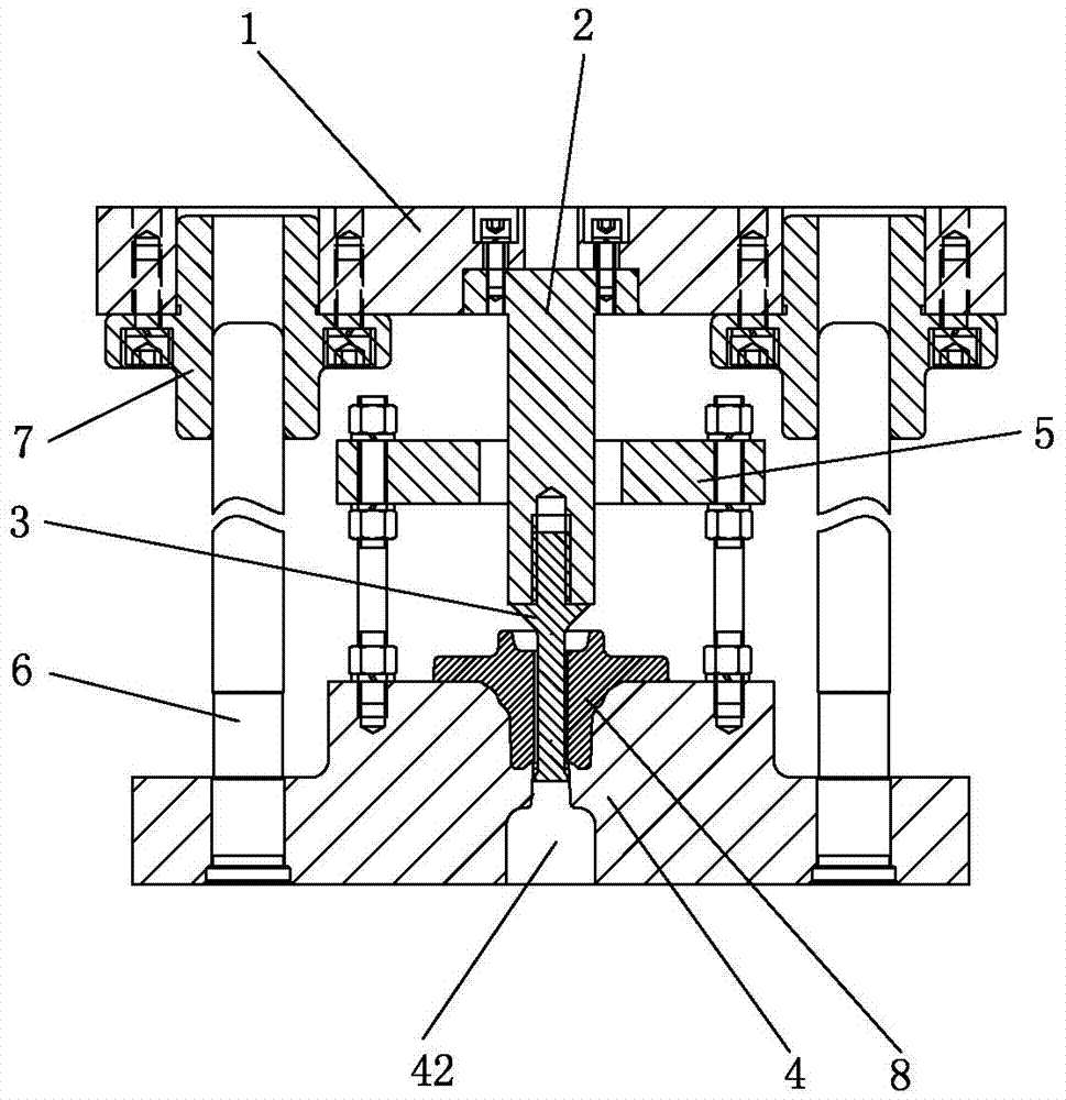
[0026] Such as figure 1 , Figure 4 , Figure 5 As shown, the wheel hub unit extrusion punching forging die of this embodiment includes an upper die and a lower die, and the upper die includes an upper die seat 1, a punch seat 2, and a punch 3, and the punch seat 2 is fixed on the upper die Seat 1, the upper end of punch 3 is fixed in punch seat 2 by screw thread, and described lower die comprises punch 4, stripping plate 5 (lower die can also comprise lower die seat, in the present embodiment, punch 4 and The lower mold base is integrated), the punch 4 is provided with a mold cavity 41 for accommodating the cylindrical end of the hub unit, the bottom of the mold cavity 41 is provided with a downwardly penetrating ejection hole 42, and the mold cavity 41 ...


PUM

PropertyMeasurementUnit
Thicknessaaaaaaaaaa

Abstract

The invention relates to the technical field of automobile hub processing, in particular to a wheel hub unit extrusion punching forging die, which includes an upper die and a lower die, the upper die includes an upper die seat, a punch seat, and a punch, and the lower die includes a punch, a discharge plate, the punch is provided with a die cavity for accommodating the cylindrical end of the hub unit, the bottom of the die cavity is provided with a downwardly penetrating ejection hole, the diameter of the die cavity is D, and the diameter of the cylindrical end of the pre-forging that is extruded and punched is d, D=d+3mm, the upper part of the mold cavity is provided with a transition arc corresponding to the root of the cylindrical end of the pre-forging, the bottom of the mold cavity is raised upwards to form a small boss, and there is a Cutting edge, the structure of the invention is scientific, the pre-forged piece is first squeezed through the punch, and the metal flows downward and circumferentially at the same time, and then the metal flowing downward is cut off under the action of the punch and the cutting edge. Extrusion and punching are completed at the same time through a set of molds, which reduces the use of molds and improves production efficiency.

Description

technical field [0001] The invention relates to the technical field of automobile wheel hubs, in particular to a wheel hub unit extrusion punching forging die. Background technique [0002] The hub unit is an important part of a car wheel. Its structure is similar to a body of revolution. The smaller end of the hub unit is a cylindrical end, and the other end is a large bowl-shaped plate. There is a through hole along the axial direction of the cylindrical end at the bottom of the large plate. through the axle. The hub unit is generally formed by forging, and then processed by gold. In the prior art, the three-step processing of billet making, pre-forging and final forging is used to form the large plate and the cylindrical end, and then the through hole of the cylindrical end is processed by drilling, reaming, and boring in the subsequent metal processing. [0003] This prior art has the following defects: 1. Since the length of the cylindrical end is about 80 mm to 120 m...

Claims


Application Information

Patent Timeline
IPC IPC(8): B21J13/00B21J5/10B21K1/40
CPCB21J13/00B21J5/10B21K1/40
Inventor 张运军晏洋陈天赋武建祥杨杰余国林李航王国文
Owner HUBEI TRI RING FORGING
Features
  • R&D
  • Intellectual Property
  • Life Sciences
  • Materials
  • Tech Scout
  • Unparalleled Data Quality
  • Higher Quality Content
  • 60% Fewer Hallucinations
Learn More