Fault injection method and system

A fault injection and fault technology, applied in the field of computer simulation, can solve problems such as unsatisfactory, unapproachable evolution environment development, complex time-space change characteristics of evolution, and difficulty in effective control

Active Publication Date: 2017-07-28
CENT SOUTH UNIV
View PDF7 Cites 11 Cited by
  • Summary
  • Abstract
  • Description
  • Claims
  • Application Information

AI Technical Summary

Problems solved by technology

[0005] The time-space variation characteristics of faults in the traction system of high-speed trains make it impossible to construct large-scale and complex faults on the traditional simulation platform with the main goal of realizing normal operation behavior by simply setting fault injection links or adding fault diagnosis functions. The architecture of the diagnostic application verification platform; it is also unable to approach the evolution environment of system faults in the fault injection mode and the complex time-space change characteristics of occurren...

Method used


Image

  • Fault injection method and system
  • Fault injection method and system
  • Fault injection method and system

Examples


Embodiment 1

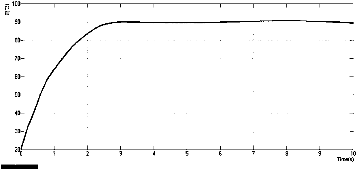
[0066] In this embodiment, a fault simulation is performed on the evolution process of the performance degradation of the power device of the rectifier circuit in the traction converter until an open-circuit fault occurs. This embodiment is performed in the virtual simulation platform Simulink software environment, and the environment defines that "0" and "1" signals represent the off and on states of the power device, respectively.

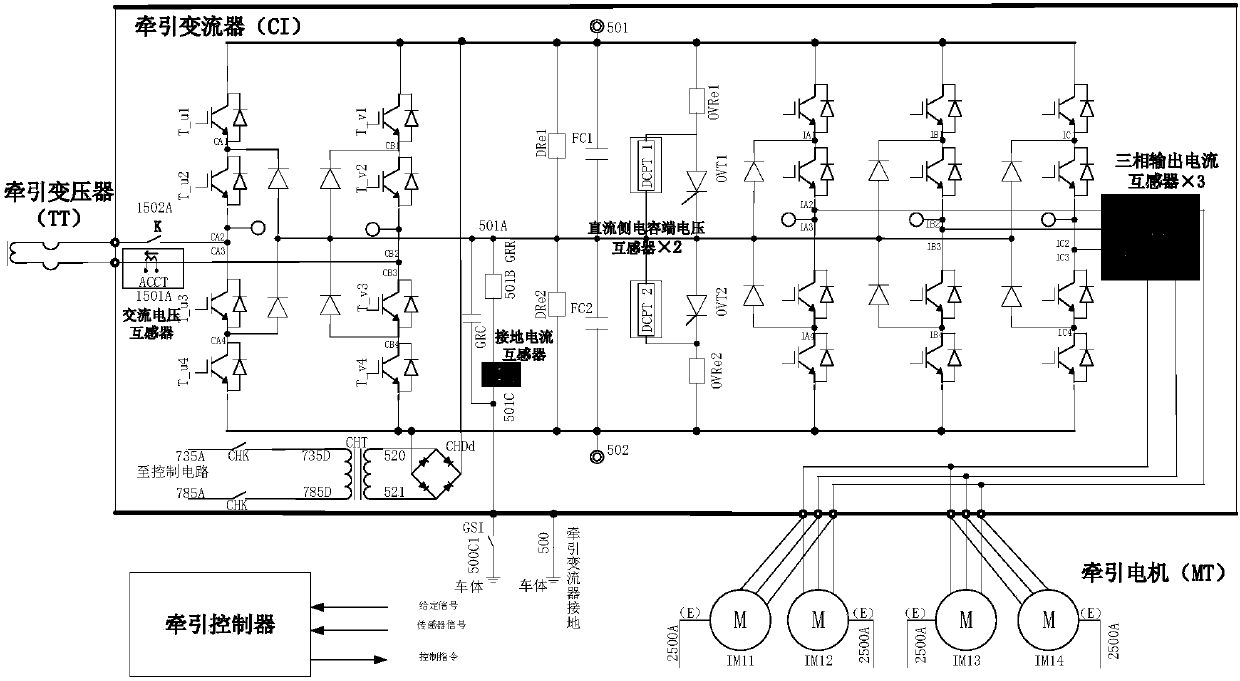
[0067] figure 1 It is a schematic diagram of the traction system of the CRH2 type high-speed train adopted in this embodiment. By receiving sensor signals and command signals, the traction controller calculates the conduction state of each power device in the converter according to the preset control algorithm, so as to realize the control of the running state of the traction system of the high-speed train; the traction converter is responsible for receiving the contact The high-voltage power grid is converted into low-voltage single-phase power...

Embodiment 2

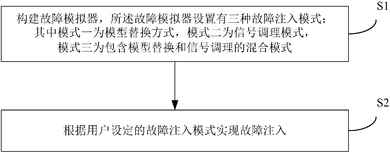
[0142] Corresponding to the above embodiments, the present embodiment discloses a fault injection system including a fault simulator. The fault simulator is provided with three fault injection modes; the first mode is a model replacement mode, the second mode is a signal conditioning mode, and the mode The third is a mixed mode including model replacement and signal conditioning; it is used to implement fault injection according to the fault injection mode set by the user. The fault injection system can be applied to simulate the fault injection of the traction drive system of high-speed trains. The corresponding fault source is composed of five parts: the traction controller, the traction transformer, the traction converter, the traction motor and the on-board sensor in the traction drive system of the high-speed train. .

[0143] like Figure 11 As shown, the fault simulator constructed in this embodiment includes a fault injection controller, and the fault injection contro...


PUM


Abstract

The invention relates to the field of computer simulation technology and discloses a fault injection method and system for simulating a fault characteristic in a reliable, safe and realistic manner. The method comprises the steps of constructing a fault simulator which is provided with a model replacement mode, a signal conditioning mode and a mixed mode including model replacement and signal conditioning; and performing fault injection according to a user-set fault injection mode. The method and system in the invention can be applied to simulate the fault injection of a high-speed train traction drive system, and the fault injection method based on signal conditioning, based on model replacement, or based on the mixed mode including model replacement and signal conditioning can be adopted according to actual needs to achieve realistic simulation various types of common faults in a traction drive control system; and the method and system in the invention provide a safe, reliable and realistic fault injection/simulation/emulation and test platform for the diagnosis of common faults in the traction drive control system, fault tolerance and other technology, and have strong applicability.

Description

technical field [0001] The invention relates to the technical field of computer simulation, in particular to a fault injection method and system applicable to simulating a fault in a high-speed train traction drive system. Background technique [0002] The safe operation of high-speed trains is the most important issue in the operation and development of high-speed railways. The rapid development of my country's high-speed railway has formed a high-speed railway technology system with Chinese characteristics. The overall technical level and application level are world-leading. Safe operation brings serious safety hazards. [0003] The high-speed train traction drive system consists of traction transformers, traction controllers, traction converters, traction motors, and on-board sensors. It is the heart (conversion) and brain (control) of high-speed trains. It is one of the key systems for high-speed train operation safety, and it is also one of the main sources of high-spe...

Claims


Application Information

Patent Timeline
IPC IPC(8): G05B23/02
CPCG05B23/0256
Inventor 阳春华杨超彭涛陶宏伟赵帅史露尹进田杨笑悦贺泽洲刘博李晟
Owner CENT SOUTH UNIV
Why Eureka
Try Eureka