
Dynamic rotation marking control system and method

A technology of control system and dynamic rotation, which is applied in the direction of manufacturing tools, welding equipment, laser welding equipment, etc., can solve the problems of low efficiency of rotary marking and unsatisfactory marking effect, and solve the problems of low efficiency of rotary marking and solution of marking The effect of unsatisfactory standard effect and simple method

Active Publication Date: 2017-08-01
HANS LASER TECH IND GRP CO LTD
View PDF6 Cites 12 Cited by
  • Summary
  • Abstract
  • Description
  • Claims
  • Application Information

AI Technical Summary

Problems solved by technology

[0003] The purpose of the present invention is to solve the technical problems existing in the prior art, to provide a dynamic rotary marking control system and control method, which can realize the simultaneous operation of laser marking and rotary shaft, thereby solving the problem of low efficiency of existing rotary marking and marking Problems with unsatisfactory results

Method used


Image

  • Dynamic rotation marking control system and method
  • Dynamic rotation marking control system and method
  • Dynamic rotation marking control system and method

Examples


Embodiment Construction

[0034] In order to facilitate the understanding of the present invention, the present invention will be described more fully below with reference to the associated drawings. Preferred embodiments of the invention are shown in the accompanying drawings. However, the present invention can be embodied in many different forms and is not limited to the embodiments described herein. On the contrary, these embodiments are provided to make the understanding of the disclosure of the present invention more thorough and comprehensive.

[0035] Unless otherwise defined, all technical and scientific terms used herein have the same meaning as commonly understood by one of ordinary skill in the technical field of the invention. The terms used herein in the description of the present invention are for the purpose of describing specific embodiments only, and are not intended to limit the present invention.

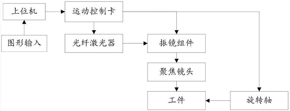
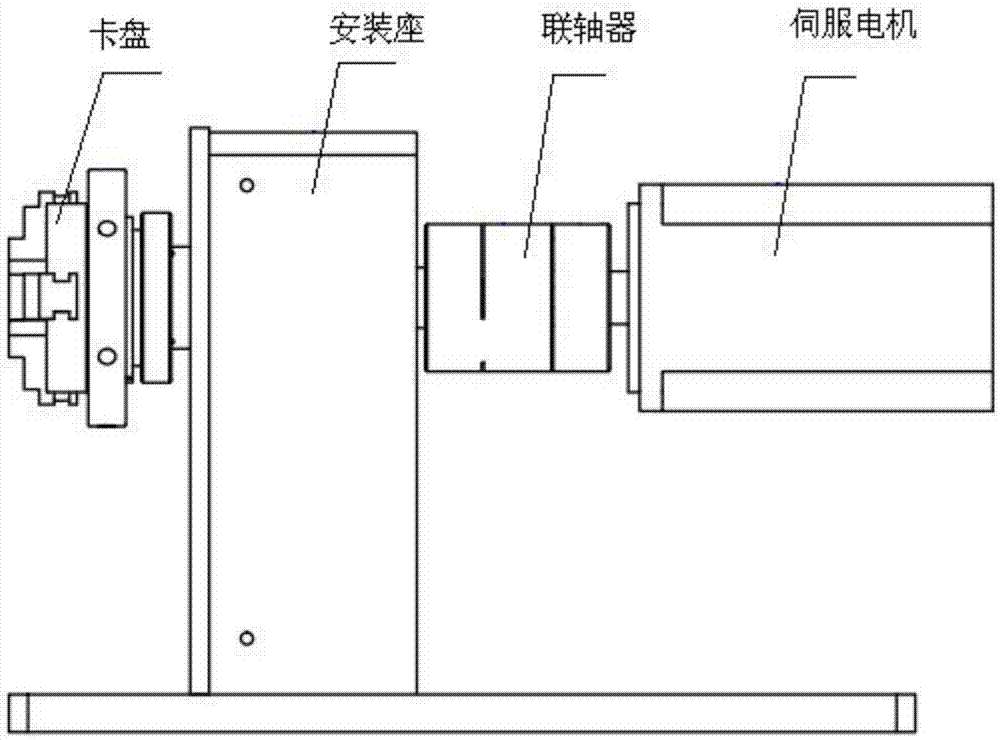
[0036] refer to figure 1 As shown, the present invention provides a dynamic rotary ...


PUM


Abstract

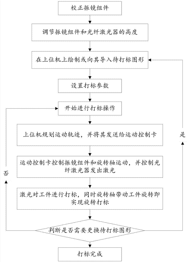
The invention relates to the technical field of laser processing, and discloses a dynamic rotation marking control system. According to the control system, an upper computer transmits control information to a motion control card, the motion control card outputs motion signals to a galvanometer assembly and a rotation shaft according to the control information, and the motion control card further outputs control signals to an optical fiber laser device and controls light emitting and light closing of the optical fiber laser device; the optical fiber laser device emits a laser according to the control signals and outputs the laser to the galvanometer assembly; the galvanometer assembly controls rotation of a reflection lens adopted in the galvanometer assembly according to the motion signals; the received laser further acts on a workpiece through a focusing lens; the rotation shaft controls rotation of the workpiece according to the motion signals, and accordingly circumferential marking of the workpiece through the laser is achieved. According to the dynamic rotation marking control system, laser marking and the rotation shaft can work at the same time, and accordingly the problems that the rotation marking efficiency is low and the marking effect is not ideal are solved.

Description

technical field [0001] The present invention relates to the technical field of laser processing, and more specifically relates to a dynamic rotary marking control system and control method. Background technique [0002] The common practice of rotary marking control systems in the market is that the laser marking and the rotation of the rotary shaft do not work at the same time, that is, the rotary shaft stops during laser marking, or the laser does not mark when the rotary shaft moves, which is called static rotary marking. mark. This brings about two major defects: 1. The efficiency of rotary marking is low due to multiple divisions of the graphics; 2. The marking effect is not ideal due to the existence of partial focus and splicing of graphics in essence. Contents of the invention [0003] The purpose of the present invention is to solve the technical problems existing in the prior art, to provide a dynamic rotary marking control system and control method, which can re...

Claims


Application Information

Patent Timeline
IPC IPC(8): B23K26/362B23K26/08
CPCB23K26/0823
Inventor 阴波波杜明李海张燚高云峰
Owner HANS LASER TECH IND GRP CO LTD
Learn More