Liquid crystal element with negative dielectric anisotropy

A technology for liquid crystal elements and liquid crystal compositions, applied in liquid crystal materials, nonlinear optics, instruments, etc., can solve the problems of low reliability of measurement results, insufficient display quality, and reduced VHR value, so as to improve display quality and reduce residual orders. effect of bulk, high voltage retention

Inactive Publication Date: 2017-08-01
DIC CORP
View PDF12 Cites 4 Cited by
  • Summary
  • Abstract
  • Description
  • Claims
  • Application Information

AI Technical Summary

Problems solved by technology

[0005] (Patent Document 1) shows a liquid crystal medium showing a high VHR value and low rotational viscosity, but when a liquid crystal medium containing more than 10% of the compound of formula (1) is used, the ratio of the remaining monomer becomes Too many, resulting in the decrease of VHR value, the increase of ID value, and the display quality is not enough
In addition, the rotation viscosity is not enough
[0006] On page 12 of (Patent Document 4), a method using gas chromatography (GC) is shown as a simple measurement method for the amount of polymerizable compounds remaining in the liquid crystal phase after polymerization, but it is difficult to quantitatively capture by GC and may become Polymeric compounds after polymerization with various molecular weights, low reliability of measurement results

Method used


Image

  • Liquid crystal element with negative dielectric anisotropy
  • Liquid crystal element with negative dielectric anisotropy
  • Liquid crystal element with negative dielectric anisotropy

Examples


Embodiment 1

[0172] Example 1 satisfies the physical property values ​​required for liquid crystal televisions, and the values ​​of VHR (after polymerization treatment) and ID (after polymerization treatment) are good. On the other hand, the liquid crystal composition of Comparative Example 1 has a large γ1 and is considered to have a long response time. The residual monomer ratio after polymerization treatment was also large, and the values ​​of VHR (after polymerization treatment) and ID (after polymerization treatment) were inferior to those of Example 1. As can be seen from the above, Example 1, which is a liquid crystal element of the present invention, satisfies various characteristics required by liquid crystal televisions, has a sufficiently small residual monomer ratio, and is excellent in reliability, and is very useful as a long-life active matrix type liquid crystal display element. .

[0173] Furthermore, Table 3 shows the liquid crystal compositions and device physical prope...

Embodiment 2

[0176] Example 2 satisfies the physical property values ​​required for liquid crystal televisions, and the values ​​of VHR (after polymerization treatment) and ID (after polymerization treatment) are good. On the other hand, the liquid crystal composition of Comparative Example 1 has a large γ1 and is considered to have a longer response time. The residual monomer ratio after polymerization treatment was also large, and the values ​​of VHR (after polymerization treatment) and ID (after polymerization treatment) were inferior to those of Example 2. As can be seen from the above, Example 2, which is a liquid crystal element of the present invention, satisfies various characteristics required by liquid crystal televisions, has a sufficiently small residual monomer ratio, and is excellent in reliability, and is very useful as a long-life active matrix type liquid crystal display element. .

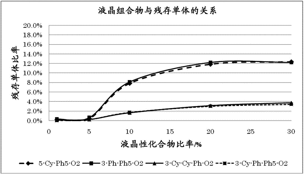
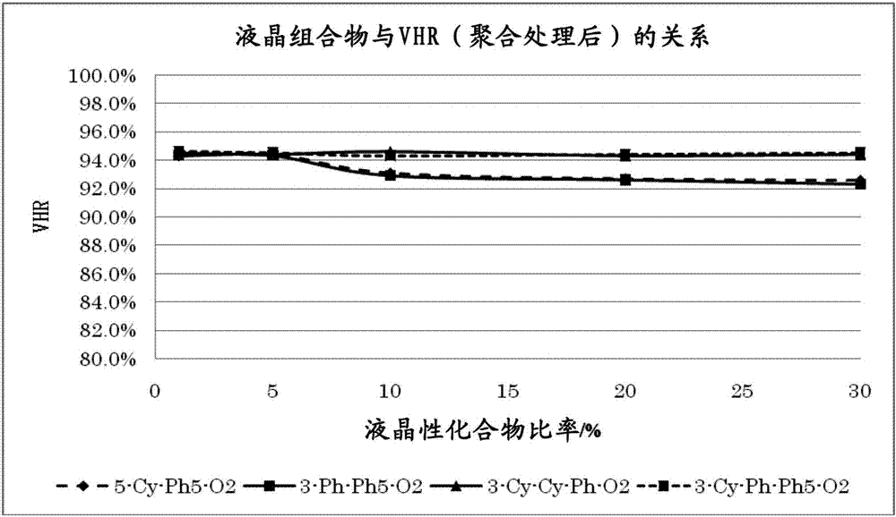
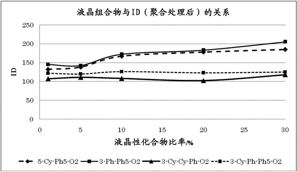
[0177] Furthermore, in order to confirm the relationship between the liquid crystal compo...


PUM


Abstract

The present invention addresses the problem of providing a liquid crystal element that sufficiently optimizes mainly the electro-optical properties of a VA display, has a wide operating temperature range, a high-speed responsiveness at a low temperature, a halftone response speed, a high contrast, a wide viewing angle, a low threshold voltage and a high resistance value, and, after polymerizing a polymerizable liquid crystal compound, contains little residual monomer and shows a high voltage retention rate. As the results of intensive studies to solve the aforesaid problem, the present inventors found the most appropriate configuration of a liquid crystal element so as to complete the present invention.

Description

technical field [0001] The present invention relates to a liquid crystal element using a negative dielectric constant anisotropic liquid crystal useful as an electro-optical liquid crystal display material. Background technique [0002] Active-matrix liquid crystal display devices appear in the market of portable terminals, liquid crystal televisions, projectors, computers, and the like because of their excellent display quality. In the active matrix display method, TFT (Thin Film Transistor) or MIM (Metal-Insulator-Metal) or the like is used for each pixel, and high voltage retention is important in this method. In addition, in order to obtain a wider viewing angle characteristic, a TFT display in combination with VA, IPS, and OCB modes has been proposed, and a reflective type in ECB mode has been proposed to obtain a brighter display. In order to cope with such display elements, new liquid crystal compounds or liquid crystal compositions have been proposed. [0003] In r...

Claims


Application Information

Patent Timeline
Patent Type & Authority Applications(China)
IPC IPC(8): C09K19/38C09K19/12C09K19/14C09K19/16C09K19/18C09K19/20C09K19/30C09K19/32C09K19/34G02F1/13G02F1/1337
CPCC09K19/30C09K2019/3009C09K2019/3027G02F1/0045C09K19/322C09K2019/0448C09K2019/3004C09K2019/301C09K2019/3016G02F1/133742G02F1/13712G02F1/13775G02F1/1337C09K19/3003C09K19/3804C09K19/3809C09K19/44C09K19/46C09K19/56G02F1/137
Inventor 金亲昌和竹内清文中田秀俊
Owner DIC CORP
Why Eureka
Try Eureka