Lamp comprising a driver circuit board and a base

A technology for driving boards and light bulbs, which is applied to lighting and heating equipment, the use of semiconductor lamps, and components of lighting devices, etc. It can solve the problems of difficulty in automation and high cost, and achieve the advantages of easy automation, safety preservation, and avoidance of short circuits Effect

Inactive Publication Date: 2017-08-01
LEDVANCE GMBH
View PDF4 Cites 5 Cited by
  • Summary
  • Abstract
  • Description
  • Claims
  • Application Information

AI Technical Summary

Problems solved by technology

The semiconductor retrofit bulb 101 has the disadvantage that the electrical connection between the drivers 107, 108 and the base 111 is expensive to produce and especially difficult to automate

Method used


Image

  • Lamp comprising a driver circuit board and a base
  • Lamp comprising a driver circuit board and a base
  • Lamp comprising a driver circuit board and a base

Examples


Embodiment Construction

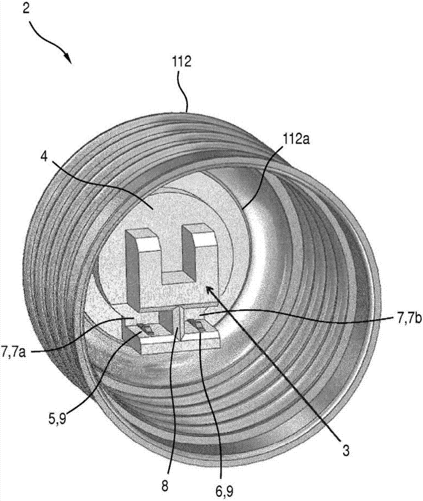
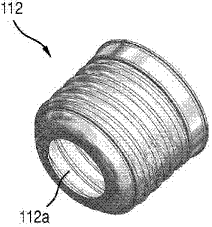
[0045] figure 2 Shown is a semiconductor retrofit bulb 1 according to the invention (see Figure 8 to Figure 10 ) oblique front view of the base 2. The base 2 configured as an Edison screw cap has image 3 The side contacts 112 are shown separately. It can be a conventional side contact 112 and is present, for example, in the form of a metal sleeve-like thread and has a front opening 112a.

[0046] In the front opening 112a a socket 3 is used positively as a socket part of the plug-in connection. The socket 3 consists of an electrically insulating plastic casting material 4 , wherein a first contact element 5 and a second contact element 6 are molded from metal with a positive fit. The first contact element 5 and the second contact element 6 are electrically separated from each other by the potting compound 4 .

[0047] The casting material 4 is the plug (see Figure 8 to Figure 10 ) provides a receiving part 7 having a first receiving area 7a and a second receiving are...


PUM


Abstract

Disclosed is a lamp (1) comprising a driver circuit board (16) and a base (2) which are electrically connected to one another by a plug connector (3, 17). The invention applies to semiconductor lamps, for example, especially LED lamps, in particular retrofit lamps, e.g. to replace conventional incandescent lamps or halogen lamps.

Description

technical field [0001] The invention relates to a light bulb, which has a driving board and a base, and is electrically connected to each other. The invention can be applied, for example, to semiconductor light bulbs, especially LED light bulbs, especially retrofit light bulbs, eg as a replacement for traditional incandescent or halogen light bulbs. Background technique [0002] There is known a LED retrofit bulb with a driver board and a base electrically connected thereto, the electrical connection to the driver board is realized by wires or wired components such as PTH fuses, ie by welding or clamping. [0003] For example, figure 1 A semiconductor retrofit bulb 101 is shown which has the form of an LED bulb retrofit bulb according to the prior art. The front side of the semiconductor retrofit bulb 101 has a light-transmitting cover 102 which covers the LED module 103 . The front side of the LED module 103 has a plurality of LED chips 104 fixed on a common substrate 10...

Claims


Application Information

Patent Timeline
Patent Type & Authority Applications(China)
IPC IPC(8): F21K9/238F21K9/90F21V5/04F21V7/00F21V23/06F21V23/00H01R12/72F21Y115/10F21Y115/30
CPCF21K9/90F21V5/04F21V7/0091F21V23/006F21V23/06H01R12/721F21K9/23F21K9/238F21Y2115/10Y02B20/30F21K9/235
Inventor 克劳斯·埃克特米夏埃尔·罗泽南尔
Owner LEDVANCE GMBH
Why Eureka
Try Eureka