Supercharge Your Innovation With Domain-Expert AI Agents!

Anisotropic conductive film and connection structure

一种各向异性、导电性膜的技术,应用在导电连接、电部件连接、连接等方向,能够解决连接电阻偏差等问题,达到确保导通、抑制制造成本的效果

Active Publication Date: 2017-08-01
DEXERIALS CORP
View PDF7 Cites 2 Cited by
  • Summary
  • Abstract
  • Description
  • Claims
  • Application Information

AI Technical Summary

Problems solved by technology

[0003] However, even if the conductive particles are uniformly arranged, when the anisotropic conductive film is used to anisotropically connect the upper and lower terminals, the conductive particles located on the edge of the terminal may flow out to the gap due to the melting of the insulating adhesive. Clamped by the terminal, there is a problem that the connection resistance varies

Method used


Image

  • Anisotropic conductive film and connection structure
  • Anisotropic conductive film and connection structure
  • Anisotropic conductive film and connection structure

Examples


Embodiment 1~4

[0103] Examples 1-4, Comparative Example 1

[0104] (1) Manufacture of anisotropic conductive film for FOG connection

[0105] The preparation includes 60 parts of phenoxy resin (thermoplastic resin) (Nippon Steel (Steel) Sumikin Co., Ltd., YP-50), 40 parts of epoxy resin (thermosetting resin) (Mitsubishi Chemical Co., Ltd., jER828), A mixed solution of 2 parts of cationic curing agent (Sanshin Chemical Industry Co., Ltd., SI-60L) of insulating resin is coated on a PET film with a film thickness of 50 μm, dried in an oven at 80°C for 5 minutes, and placed in a An adhesive layer with a thickness of 20 μm was formed on the PET film.

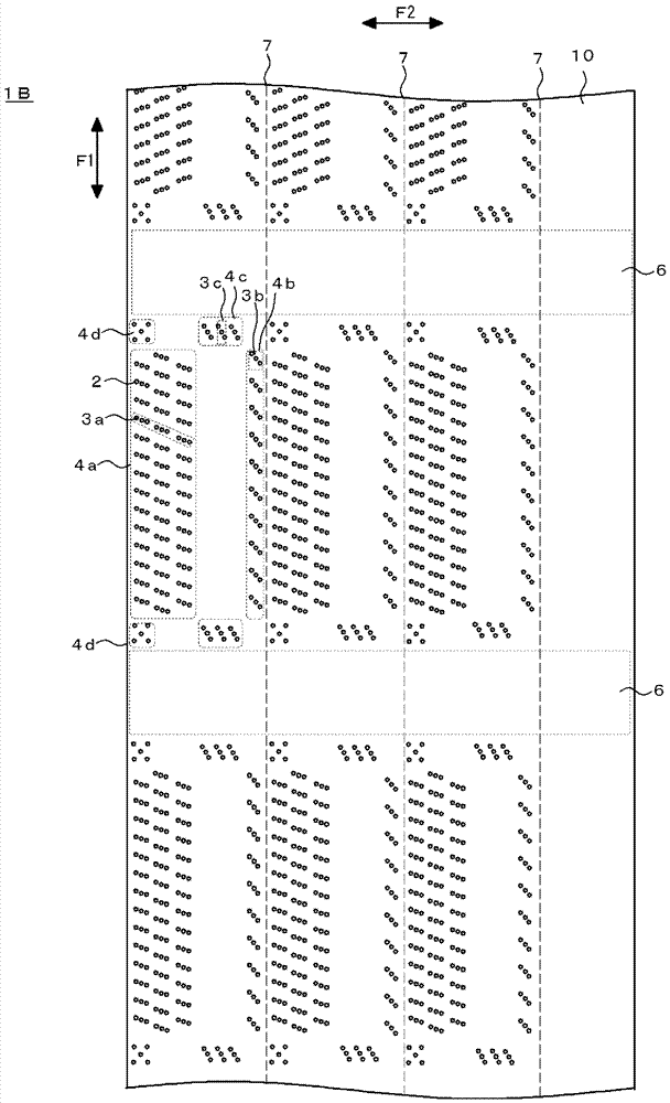
[0106] On the other hand, according to the arrangement of the electrode terminals of the FOG-connected substrate, a mold in which the protrusions periodically have an arrangement pattern with a predetermined arrangement density (Examples 1 to 4) or a mold in which the protrusions are randomly arranged with a predetermined arrangement density (Comp...

Embodiment 5~9、 comparative example 2

[0132] (1) Manufacture of anisotropic conductive film for COG connection

[0133] In the same manner as in Example 1, 60 parts of phenoxy resin (thermoplastic resin) (Nippon Steel & Sumitomo Metal Co., Ltd., YP-50) and epoxy resin (thermosetting resin) (Mitsubishi Chemical Co., Ltd., jER828) were used. 40 parts and 2 parts of cationic curing agent (Sanshin Chemical Industry Co., Ltd., SI-60L) were used to form an adhesive layer with a thickness of 20 μm on the PET film.

[0134] On the other hand, according to the bump arrangement of the IC chip connected by COG, a mold with an arrangement pattern in which the protrusions periodically have a predetermined arrangement density (Examples 5 to 9) or a 4-square grid of protrusions (grid pitch 8 μm) was produced. The mold (comparative example 2) was poured into the mold in the state where the particles of the known transparent resin were melted, cooled and solidified, and a resin mold in which the recesses were in a lattice pattern ...

Embodiment 10~14

[0160] In Examples 5 to 9, 20 parts of quartz filler (quartz particles, AEROSIL RY200, Japan AEROSIL Co., Ltd.) were added to 100 parts of insulating resin, and anisotropic conductive films were produced in the same manner as in Examples 5 to 9, and Continuity evaluation was performed. The results were all good.


PUM


Abstract

An anisotropic conductive film which is able to be used for fine-pitch FOG connection or COG connection, and which is capable of suppressing increase in the production cost due to increase of the conductive particle density. This anisotropic conductive film comprises an insulating adhesive layer and conductive particles arranged in the insulating adhesive layer. This anisotropic conductive film has conductive particle arrangement regions that are arranged corresponding to the arrangement of terminals of an electronic component to which the anisotropic conductive film is connected. The conductive particle arrangement regions are periodically formed in the longitudinal direction of the anisotropic conductive film. In addition, this anisotropic conductive film has a buffer region, where conductive particles are not arranged, between every adjacent conductive particle arrangement regions for connection.

Description

technical field [0001] The present invention relates to an anisotropic conductive film, a connection method using the anisotropic conductive film, and a connection structure connected by the anisotropic conductive film. Background technique [0002] Anisotropic conductive films are widely used when electronic components such as IC chips are mounted on substrates. In recent years, high-density wiring has been demanded in small electronic devices such as mobile phones and notebook computers. As a method for making anisotropic conductive films correspond to the high density, it is known that the insulation of anisotropic conductive films A technique in which conductive particles are evenly arranged in a grid pattern in an adhesive layer. [0003] However, even if the conductive particles are uniformly arranged, when the anisotropic conductive film is used to anisotropically connect the upper and lower terminals, the conductive particles located on the edge of the terminal may ...

Claims


Application Information

Patent Timeline
Patent Type & Authority Applications(China)
IPC IPC(8): H01R11/01H05K3/32
CPCH01R13/2414H05K3/323H01B1/20H01R11/01H05K3/32H01B5/14
Inventor 林慎一齐藤雅男塚尾怜司阿久津恭志
Owner DEXERIALS CORP
Features
  • R&D
  • Intellectual Property
  • Life Sciences
  • Materials
  • Tech Scout
  • Unparalleled Data Quality
  • Higher Quality Content
  • 60% Fewer Hallucinations
Learn More