Spiral bevel gear swing rolling formation method

A technology of spiral bevel gear and tooth shape, which is applied in the field of spiral bevel gear rotary rolling, can solve the problems of spiral bevel gear tooth shape complex, tooth shape is difficult to fill, metal flow is difficult, etc., to improve the mechanical properties of gears, tooth shape filling Plumping, low-cost results

Active Publication Date: 2017-08-04
WUHAN UNIV OF TECH
View PDF8 Cites 4 Cited by
  • Summary
  • Abstract
  • Description
  • Claims
  • Application Information

AI Technical Summary

Problems solved by technology

The complex geometry of the spiral bevel gear poses a serious challenge to its manufacture. If it is manufactured by integral die forging, it will face the following three bottleneck problems: (1) Due to the complex tooth shape of the spiral bevel gear, it is easy to have difficulty in metal flow during the forming process. Deformation dead zone, so the tooth shape is difficult to fill; (2) The forming force is large, the tooth shape accuracy is low, and the mold life is low; (3) Because the tooth shape is helical, it is difficult to demold the gear after forming
However, there is currently no design for spiral bevel gears whose complex tooth profiles are formed by complex dynamic oscillating head oscillations.

Method used


Image

  • Spiral bevel gear swing rolling formation method
  • Spiral bevel gear swing rolling formation method
  • Spiral bevel gear swing rolling formation method

Examples


Embodiment Construction

[0023] In order to make the object, technical solution and advantages of the present invention clearer, the present invention will be further described in detail below in conjunction with the accompanying drawings and embodiments. It should be understood that the specific embodiments described here are only used to explain the present invention, not to limit the present invention.

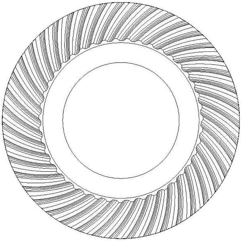
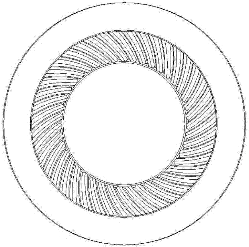
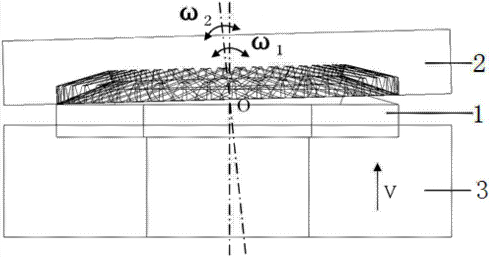
[0024] Such as Figure 1-Figure 4 As shown, a spiral bevel gear rotary rolling forming method, the spiral bevel gear is formed by rotary rolling mold, such as image 3 As shown, the oscillating rolling mold includes a oscillating head 2 and a oscillating rolling lower mold 3 arranged up and down oppositely, the oscillating head 2 moves in a circular trajectory, and the oscillating rolling lower mold 3 moves upward in a straight line. The forming method of the oscillating rolling includes the following steps : The spiral bevel gear blank 1 is placed between the swing head 2 and the swing die 3, the...


PUM

PropertyMeasurementUnit
modulusaaaaaaaaaa
angleaaaaaaaaaa
angleaaaaaaaaaa

Abstract

The invention discloses a spiral bevel gear swing rolling formation method. A spiral bevel gear is formed in a swing rolling manner by a swing rolling mold; the swing rolling mold includes a swing head and a swing rolling lower mold oppositely arranged up and down; the swing head performs a circular trajectory motion; the swing rolling lower mold performs an upward linear feeding motion; and the swing rolling formation method comprises the following steps: a spiral bevel gear blank is placed between the swing head and the swing rolling lower mold; a tooth shape of the spiral bevel gear is formed through swinging of the swing head; and the spiral bevel gear and a back part opposite to the tooth shape are formed by the swing rolling lower mold. The spiral bevel gear swing rolling formation method can refine grains and densify streamlines to greatly improve the gear mechanical performances, is low in forming force, high in tooth shape precision, long in mold life and liable to demold, and has the advantages of high production efficiency, high material utilization rate and low cost.

Description

technical field [0001] The invention belongs to the technical field of gear forming and manufacturing, and in particular relates to a method for forming spiral bevel gears by swing rolling. Background technique [0002] Spiral bevel gears are the most complex gears in geometry and transmission. They have significant advantages such as high transmission efficiency, large overlap coefficient, high load capacity, stable transmission, long life, and low noise. They are widely used in aviation, aerospace, ships, high-speed rail, wind power, It is widely used in high-end equipment fields such as high-end automobiles and high-end machine tools. The complex geometry of the spiral bevel gear poses a serious challenge to its manufacture. If it is manufactured by integral die forging, it will face the following three bottleneck problems: (1) Due to the complex tooth shape of the spiral bevel gear, it is easy to have difficulty in metal flow during the forming process. Deformation dead...

Claims


Application Information

Patent Timeline
Patent Type & Authority Applications(China)
IPC IPC(8): B21J5/02B21J13/02B21K1/30
CPCB21J5/02B21J13/02B21K1/305
Inventor 韩星会华林胡亚雄冯玮
Owner WUHAN UNIV OF TECH
Why Eureka
Try Eureka