Optical fiber temperature sensing device

A technology for sensing device and optical fiber temperature, applied in thermometers, measuring devices, thermometers with physical/chemical changes, etc., can solve the problems that optical fiber sensors cannot take into account high sensitivity, anti-interference and simple demodulation methods, etc., to increase practicality Value, low phase noise, low phase noise effect

Active Publication Date: 2017-08-04
HUAZHONG UNIV OF SCI & TECH
View PDF5 Cites 4 Cited by
  • Summary
  • Abstract
  • Description
  • Claims
  • Application Information

AI Technical Summary

Problems solved by technology

[0006] In view of the above defects, the object of the present invention is to provide an optical fiber temperature sensing device, which aims to solve the technical problem that the optical fiber sensor cannot take into account high sensitivity, anti-interference and simple demodulation method due to the structure of the optical fiber sensor in the prior art

Method used


Image

  • Optical fiber temperature sensing device
  • Optical fiber temperature sensing device
  • Optical fiber temperature sensing device

Examples


Embodiment Construction

[0041] In order to make the object, technical solution and advantages of the present invention more clear, the present invention will be further described in detail below in conjunction with the accompanying drawings and embodiments. It should be understood that the specific embodiments described here are only used to explain the present invention, not to limit the present invention.

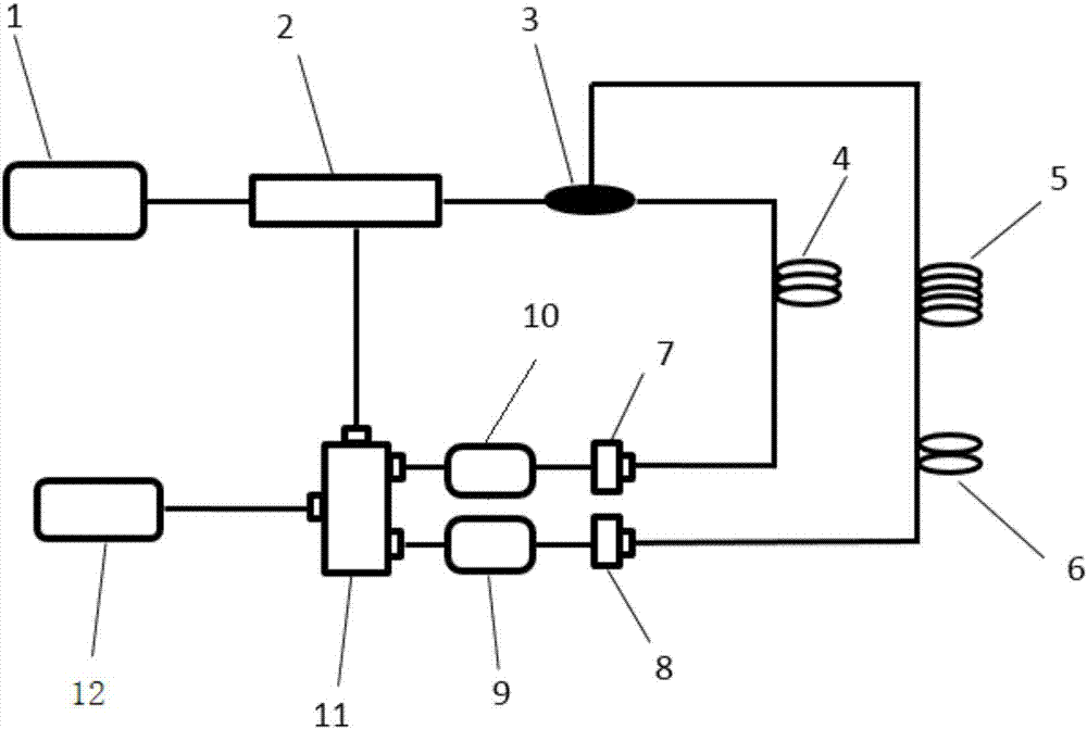
[0042] figure 1 The schematic diagram of the structure of the optical fiber temperature sensing device provided by the present invention, the optical fiber temperature sensing device includes a photoelectric modulation unit 2 and a beam splitting unit 3, the input end of the photoelectric modulation unit 2 is used to connect with the output end of the laser generating unit 1, and the photoelectric modulation unit 2 is used to connect with the output end of the laser generating unit 1. The modulating unit 2 is used for modulating the laser signal output by the laser generating unit 1 according to...


PUM


Abstract

The invention discloses an optical fiber temperature sensing device, which comprises a photoelectric modulation unit, a beam splitting unit, a first branch, a second branch and a beam combining unit, and is characterized in that the photoelectric modulation unit, the beam splitting unit, the first branch and the beam combining unit form a first oscillation circuit, the first oscillation circuit is used for realizing oscillation of a first microwave signal, the photoelectric modulation unit, the beam splitting unit, the second branch and the beam combining unit form a second oscillation circuit, the second oscillation circuit is used for realizing oscillation of a second microwave signal, a resonant wave is acquired through performing superposition processing on the first microwave signal and the second microwave signal, the oscillation peak of the resonant wave shifts when a temperature signal is loaded to a sensing region in a second optical fiber, and demodulation for the temperature signal can be realized through acquiring intensity variations of the resonant wave at a fixed frequency. The optical fiber temperature sensing device provided by the invention is high in sensitivity, high in anti-interference ability, low in phase noise, wide in measurement range and simple in demodulation, and can be applied to optical fiber communication.

Description

technical field [0001] The invention belongs to the technical field of optical fiber sensing, and more specifically relates to an optical fiber temperature sensing. [0002] technical background [0003] The development of optical fiber sensing technology began in the 1970s, and it is one of the most active branches of optoelectronic technology. Because the optical fiber has many characteristics such as high sensitivity, anti-electromagnetic interference, small size, and easy formation of arrays. Therefore, the optical fiber sensing technology has received great attention since it came out, and has been researched and applied in almost every field. It has become the forerunner of sensing technology and promoted the vigorous development of sensing technology. [0004] Compared with traditional sensors, the use of optical fibers for sensing has many advantages: optical fibers are small in size and light in weight, and are easy to embed in the structure to be tested; they have ...

Claims


Application Information

Patent Timeline
Patent Type & Authority Applications(China)
IPC IPC(8): G01K11/32G01K11/3206
CPCG01K11/32
Inventor 夏历刘康
Owner HUAZHONG UNIV OF SCI & TECH
Why Eureka
Try Eureka