Device for butted splicing of annular support grid and section sample for transmission electron microscope

A transmission electron microscope and ring-shaped technology, which is applied in the field of preparation of transmission electron microscope section samples, can solve problems such as difficult to control the distance between glue points on both sides and the amount of glue dispensed, so as to improve the success rate of sample preparation and work efficiency, and reduce pollution.

Active Publication Date: 2017-08-04
GUANGXI UNIV
View PDF22 Cites 1 Cited by
  • Summary
  • Abstract
  • Description
  • Claims
  • Application Information

AI Technical Summary

Problems solved by technology

[0005] The object of the present invention is to provide a device for bonding the annular carrier grid and the cross-sectional sample for transmission electron microscopy, thereby overcoming the existing annular carrier grid and cross-sectional sample. It is difficult to control the distance between the glue dots on both sides and the glue volume of the glue dots, and it is difficult to accurately glue the glue.

Method used


Image

  • Device for butted splicing of annular support grid and section sample for transmission electron microscope
  • Device for butted splicing of annular support grid and section sample for transmission electron microscope
  • Device for butted splicing of annular support grid and section sample for transmission electron microscope

Examples


Embodiment Construction

[0020] The specific embodiments of the present invention will be described in detail below in conjunction with the accompanying drawings, but it should be understood that the protection scope of the present invention is not limited by the specific embodiments.

[0021] Unless expressly stated otherwise, throughout the specification and claims, the term "comprise" or variations thereof such as "includes" or "includes" and the like will be understood to include the stated elements or constituents, and not Other elements or other components are not excluded.

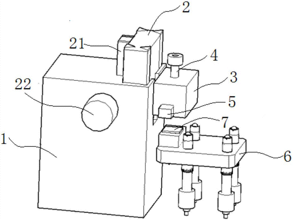
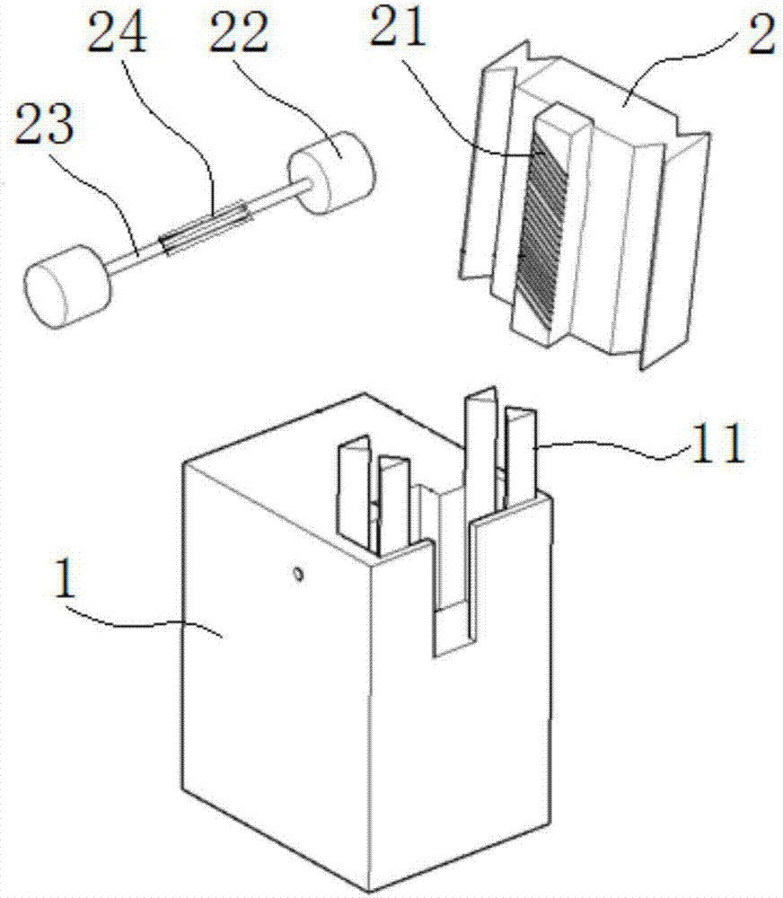
[0022] Figure 1 to Figure 5 It shows a structural schematic diagram of a device for adhering an annular grid of a transmission electron microscope to a cross-section sample according to a preferred embodiment of the present invention. The device for adhering the annular grid of a transmission electron microscope to a cross-section sample includes a lifting base 1. Lifting body 2, sticking table 3, sticking column 4, slide...


PUM

PropertyMeasurementUnit
diameteraaaaaaaaaa

Abstract

The invention discloses a device for butted splicing of an annular support grid and a section sample for a transmission electron microscope. The device comprises a lifting pedestal, a lifting body, a butted splicing table, a butted splicing column, a slide block and a retaining pin, wherein the lifting body is arranged on the lifting pedestal and is driven by a lifting mechanism to life; the butted splicing table is arranged on the lifting body and is locked on the lifting body through a locking mechanism; a longitudinally distributed column hole is formed in the butted splicing table, and an upper step is arranged on the upper portion of the column hole; a lower step is arranged on the lower end of the butted splicing column, the lower portion of the butted splicing column is movably sleeved in the column hole, and a spring clamped between the lower step and the upper step sleeves on the butted splicing column; the slide block is arranged in the bottom of the butted splicing table in a sliding manner; and the retaining pin is fixed on the slide block which can pushes the retaining pin to the lower end of the column hole. According to the device disclosed by the invention, the distance and dispense volume of dispensing points on the annular support grid can be regulated conveniently, and the annular support grid with the dispensing points is quickly and precisely centered and adhered to the section sample on a grinding machine.

Description

technical field [0001] The invention relates to the field of preparation of cross-sectional samples for transmission electron microscopy, in particular to a device for adhering a circular carrier grid of a transmission electron microscope to a cross-sectional sample. Background technique [0002] There are usually two methods for preparing cross-sectional samples of transmission electron microscopy (TEM): one is to use the focused ion beam (FIB) technology that requires relatively high equipment and experience; Ion thinning techniques for TEM samples. At present, the steps of ion thinning sample preparation for cross-sectional samples are roughly as follows: cutting (cutting the cross-sectional sample bonded to the Si wafer into small pieces whose diagonal line does not exceed 3mm and thickness does not exceed several hundred microns)→grinding (cutting The sample is fixed on the glass column on the grinder and ground until the Si sheet transmits red light)→paste the ring gr...

Claims


Application Information

Patent Timeline
Patent Type & Authority Applications(China)
IPC IPC(8): G01N1/28
CPCG01N1/28
Inventor 王双宝沈培康田植群尹诗斌朱莉安·D·V·凯潘智毅
Owner GUANGXI UNIV
Why Eureka
Try Eureka