
A parallel double gas chamber trace gas analysis system and gas concentration calculation method

A trace gas and analysis system technology, which is applied in the direction of material analysis, material analysis by optical means, and measurement devices, can solve the problems of increasing equipment cost, increasing equipment volume, and accumulating a large amount of calibration data to achieve accurate inversion. Effect

Active Publication Date: 2019-08-16
WUHAN MIZI ENERGY SCI & TECH CO LTD +1
View PDF4 Cites 0 Cited by
  • Summary
  • Abstract
  • Description
  • Claims
  • Application Information

AI Technical Summary

Problems solved by technology

[0003] Existing TDLAS systems often have only one analytical gas chamber, in which the gas to be measured is irradiated by laser light to form corresponding spectral signals, but because the properties of the gas itself are affected by temperature and pressure, the same concentration of gas at different temperatures The broadening and height of the absorption spectrum are different, so it is generally necessary to carry out constant temperature heat tracing treatment on the gas chamber, plus algorithms such as absorption line positioning and temperature correction to reduce the influence of unstable factors, and the tunable semiconductor (DFB) laser used in the system, There are high requirements for laser spectral line width, side mode suppression ratio and stability, and this kind of laser is relatively expensive
To sum up, the application of constant temperature system, precision components and correction algorithm will greatly increase the cost of equipment and increase the volume of equipment. More importantly, the determination of various correction parameters requires a large amount of calibration data accumulation, and the measurement concentration cannot be fully guaranteed in the long run. the accuracy of

Method used


Image

  • A parallel double gas chamber trace gas analysis system and gas concentration calculation method
  • A parallel double gas chamber trace gas analysis system and gas concentration calculation method
  • A parallel double gas chamber trace gas analysis system and gas concentration calculation method

Examples


Embodiment Construction

[0040] The following will clearly and completely describe the technical solutions in the embodiments of the present invention with reference to the accompanying drawings in the embodiments of the present invention. Obviously, the described embodiments are only some, not all, embodiments of the present invention. Based on the embodiments of the present invention, all other embodiments obtained by persons of ordinary skill in the art without making creative efforts belong to the protection scope of the present invention.

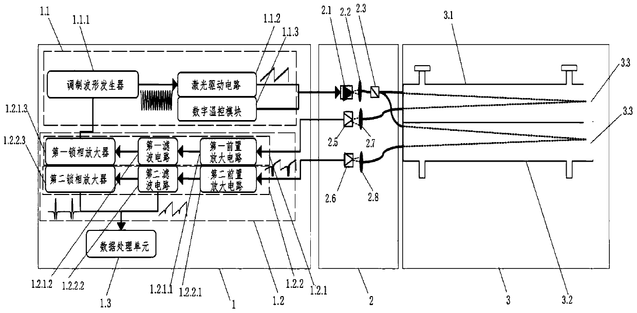
[0041] like figure 1A parallel double gas chamber trace gas analysis system is shown, including a circuit module 1, an optical module 2 and a gas path module 3,

[0042] The circuit module 1 is divided into a control circuit 1.1, a signal processing circuit 1.2 and a data processing unit 1.3, and the control circuit 1.1 includes a modulation waveform generator 1.1.1, a laser drive circuit 1.1.2 and a digital temperature control module 1.1.3, The modulation wa...


PUM


Abstract

The invention provides a parallel double-gas chamber trace gas analysis system. The system is characterized in that the system comprises a circuit module, an optical module and a gas passage module, and a laser driving circuit and a digital temperature control module are connected to a laser; the beam splitter divides laser lights into two beams, and the two beams are respectively connected to the laser incident interfaces of a standard gas chamber and a sample gas chamber through optical fibers; laser emitting interfaces which are connected to the standard gas chamber and the sample gas chamber through optical fibers are respectively connected to a second collimating convergence lens and a third collimation convergence lens through optical fibers; and a first photodiode detector is connected to a first preamplifier circuit, and a second photodiode detector is connected to a second preamplifier circuit. The system eliminates the influences of wavelength drift, the temperature pressure change and other unstable factors of the laser in a TDLAS technology, the laser performance error tolerating rate of the system is improved, and the adaptation to environment is improved.

Description

technical field [0001] The invention relates to a parallel double gas chamber trace gas analysis system and a gas concentration calculation method. Background technique [0002] Tunable Diode Laser Absorption Spectroscopy (TDLAS, Tunable Diode Laser Absorption Spectroscopy) is a technology widely used in the detection of trace gas concentration. It is widely used in petrochemical, environmental detection, biomedicine, aerospace and other fields, with selective Good, high precision, real-time non-contact and other advantages. TDLAS technology is based on the principle of molecular absorption spectroscopy. Due to the vibration form of different gas molecules, the molecules will absorb laser light of a specific wavelength. After the pool, the attenuation intensity of the outgoing light intensity is proportional to the gas concentration. In practical applications, the driving current of the laser increases the high-frequency sinusoidal modulation current to reduce the interfer...

Claims


Application Information

Patent Timeline
Patent Type & Authority Patents(China)
IPC IPC(8): G01N21/39G01N21/01
CPCG01N21/01G01N21/39
Inventor 胡雪蛟向柳
Owner WUHAN MIZI ENERGY SCI & TECH CO LTD
Learn More