System for testing electrothermal characteristics of LED light, and application of system
A technology for testing systems and thermal characteristics, which is applied in diode testing, optical performance testing, single semiconductor device testing, etc. It can solve problems such as large testing errors, low measurement accuracy, and complicated measurement processes, and achieve accurate temperature/voltage relationships and improve The accuracy of the test and the effect of the simple test process
- Summary
- Abstract
- Description
- Claims
- Application Information
AI Technical Summary
Problems solved by technology
Method used
Image

Examples
Embodiment 1
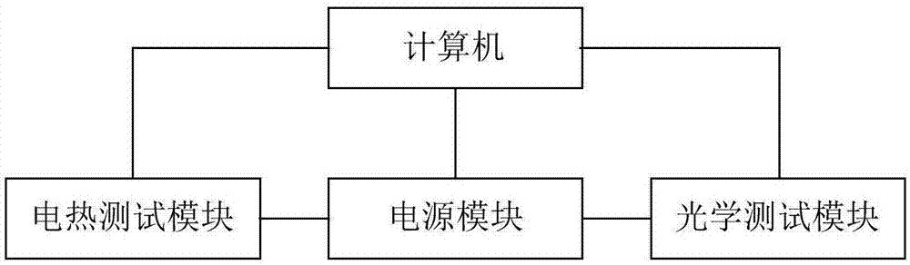
[0046] Such as figure 1 shown.
[0047] A test system for LED photoelectric and thermal characteristics, including a computer, a power supply module, an electrothermal test module and an optical test module; the computer is respectively connected to the power supply module, the electrothermal test module and the optical test module; Connect to the optical test module.
Embodiment 2
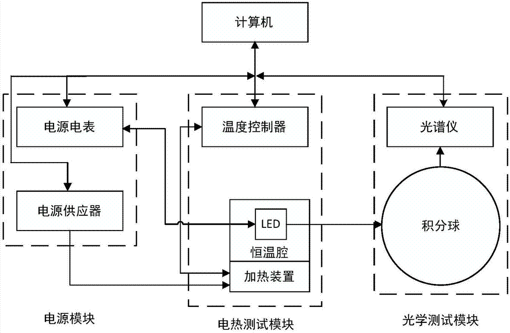
[0049] Such as figure 2 shown.
[0050] The test system for LED photoelectric thermal characteristics as described in Example 1, the difference is that the power module includes a power meter and a power supply; the electrothermal test module includes a constant temperature chamber, a heating device and a temperature controller, and the constant temperature chamber An LED is arranged inside; the optical test module includes an integrating sphere and a spectrometer; the power meter is connected to the computer and the LED respectively, and the computer is connected to the heating device through a power supply; the temperature controller is connected to the heating device and the computer respectively; The integrating sphere is respectively connected with the spectrometer and the LED, and the spectrometer is connected with the computer. When measuring the relationship between I / V and temperature, the power supply ammeter supplies LED pulse current, and when measuring the spect...
Embodiment 3
[0053] The test system for the photoelectric and thermal characteristics of LEDs described in Example 2 is different in that an LED lamp holder is provided on the integrating sphere.
PUM
 Abstract
Description
Claims
Application Information
 - Generate Ideas
- Intellectual Property
- Life Sciences
- Materials
- Tech Scout
- Unparalleled Data Quality
- Higher Quality Content
- 60% Fewer Hallucinations
Browse by: Latest US Patents, China's latest patents, Technical Efficacy Thesaurus, Application Domain, Technology Topic, Popular Technical Reports.
© 2025 PatSnap. All rights reserved.Legal|Privacy policy|Modern Slavery Act Transparency Statement|Sitemap|About US| Contact US: help@patsnap.com