Method for measuring hysteresis loop of transformer core material under harmonic excitation

A hysteresis loop and measurement method technology, which is applied in hysteresis curve measurement, magnetic performance measurement, etc., can solve the problems of method error, inability to accurately determine the magnetic circuit length, quantity and quality requirements, etc., and achieve accurate calculation Effect

Active Publication Date: 2017-08-04
HEBEI UNIV OF TECH
View PDF3 Cites 11 Cited by
  • Summary
  • Abstract
  • Description
  • Claims
  • Application Information

AI Technical Summary

Problems solved by technology

[0004] In the traditional hysteresis loop measurement method, such as the Chinese national standard: GB / T3655-2000 "Method for Measuring Magnetic Properties of Electrical Steel Sheet (Strip) with Epstein Square", Epstein Square consists of 4 coils Composition, the sample to be tested is inserted into it, and a square magnetic circuit is formed in the form of a double connection. According to the law of electromagnetic induction and the law of Ampere's loop, the magnetic induction and magnetic field strength can be measured, but the premise is that the magnetic field along the magnetic circuit must be Evenly distributed, the Epstein square circle measurement method is widely used, but there are many shortcomings: it is required to use electrical steel samples of specified size, which requires both quantity and quality; and the effective magnetic circuit length cannot be accurately determined
[0005] The ring sample measurement method is different from the Epstein square circle method. The obtained magnetization characteristics are the relationship between the average magnetic flux density and the magnetic field strength. The magnetic flux density is also measured according to the law of electromagnetic induction, and the current is obtained by the resistance method and then the magnetic field is calculated. strength, but there are also many shortcomings: due to the difference between the length of the inner and outer magnetic circuits of the ring sample, the method itself has an irremovable error factor; compared with the Epstein square method, the magnetic properties measured by the ring sample method Worse, it may be due to the stress in the sample caused by incomplete annealing, the destruction of the interlayer insulation of the sample makes eddy current appear, and the magnetic circuit length cannot be accurately determined

Method used


Image

  • Method for measuring hysteresis loop of transformer core material under harmonic excitation
  • Method for measuring hysteresis loop of transformer core material under harmonic excitation
  • Method for measuring hysteresis loop of transformer core material under harmonic excitation

Examples


Embodiment 1

[0078] In this embodiment, both the large transformer core model and the small transformer core model are made of core material B30P105 oriented silicon steel sheet, the given fundamental wave amplitude is 93V, 30% of the third harmonic is superimposed, and the phase difference between the harmonic and the fundamental wave is Δθ = π / 6. The model of the signal generator is WF1974, the model of the power amplifier is NF4520A, and the model of the power analyzer is LMG500.

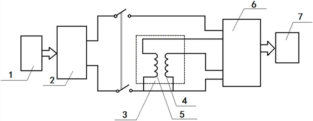
[0079] A, make the device used in the hysteresis loop measurement method of the transformer core material under harmonic excitation, the signal generator, the power amplifier, the transformer core model, the power analyzer, the recording equipment according to figure 1 Connect the device used for the measurement method of the hysteresis loop under harmonic excitation of the transformer core material constituting this embodiment.

[0080]The signal generator is connected to the input end of the power amplifie...

Embodiment 2

[0108] In this embodiment, both the large transformer core model and the small transformer core model are made of core material B30P105 oriented silicon steel sheet, the given fundamental wave amplitude is 93V, 30% of the third harmonic is superimposed, and the phase difference between the harmonic and the fundamental wave is Δθ = 0°. The remaining steps are the same as above, and the obtained hysteresis loop is as follows Figure 7 shown, Figure 7 The middle abscissa is the magnetic field intensity, the unit is A / m, and the ordinate is the magnetic induction intensity, the unit is Tesla.

Embodiment 3

[0110] In this embodiment, both the large transformer core model and the small transformer core model are made of core material B30P105 oriented silicon steel sheet, the given fundamental wave amplitude is 93V, 30% of the fifth harmonic is superimposed, and the phase difference between the harmonic and the fundamental wave Δθ=0°. The remaining steps are the same as above, and the obtained hysteresis loop is as follows Figure 8 shown, Figure 8 The middle abscissa is the magnetic field intensity, the unit is A / m, and the ordinate is the magnetic induction intensity, the unit is Tesla.

[0111] Compared Figure 6-8 It can be seen that the harmonic order, content, and phase difference superimposed on the fundamental wave will have a great impact on the hysteresis loop of the transformer core material, and the hysteresis loop under complex working conditions cannot be replaced by a simple magnetization curve. The present invention The device used in the method is consistent wi...


PUM


Abstract

The invention relates to a method for measuring the hysteresis loop of a transformer core material under harmonic excitation. Because the method gives consideration to the operation condition of a power transformer under the working condition of non-sine excitation, compared with the measurement data obtained by a conventional single-chip measurement system and an Epstein square measurement device under the standard sine excitation, the magnetic flux and hysteresis loop obtained in the mode of harmonic excitation are closer to the magnetic characteristics of the transformer core material under the harmonic excitation during working. The method is more accurate in calculation of three-dimensional finite element simulation analysis of the core material, and has the guide significance for the optimization and design of the structure of the transformer core.

Description

technical field [0001] The invention relates to the measurement of hysteresis curves of transformers, in particular to a method for measuring hysteresis loops of transformer iron core materials under harmonic excitation. Background technique [0002] With the rapid development of my country's power system and the wide application of power electronic devices, the harmonic problems of transformers are becoming more and more serious. When a transformer operates in a harmonically excited environment, it will generate a large amount of loss and generate heat, which will seriously affect the service life of the transformer and the safe operation of the power grid. It is of great significance to study the influence of harmonic excitation conditions on transformers for electromagnetic design, structural optimization and safe operation of power grids. [0003] Traditional hysteresis loop measurement methods, such as the traditional Epstein square circle measurement method and ring s...

Claims


Application Information

Patent Timeline
Patent Type & Authority Applications(China)
IPC IPC(8): G01R33/14
CPCG01R33/14
Inventor 赵志刚戎静怡魏鹏李兴刘福贵
Owner HEBEI UNIV OF TECH
Why Eureka
Try Eureka