A Low-Profile Omnidirectional Scanning End-Fire Antenna Array

An end-fire antenna and low-profile technology, applied in the field of low-profile end-fire antenna arrays, can solve the problems of inability to meet the requirements of low profile, extremely poor active standing wave, low antenna efficiency, etc., to overcome the extremely low antenna efficiency, Reduce the profile and achieve the effect of omnidirectional scanning

Active Publication Date: 2020-05-22
UNIV OF ELECTRONICS SCI & TECH OF CHINA
View PDF4 Cites 0 Cited by
  • Summary
  • Abstract
  • Description
  • Claims
  • Application Information

AI Technical Summary

Problems solved by technology

2. The end-fire array composed of antenna elements with omnidirectional radiation characteristics has very poor active standing waves and low antenna efficiency.
3. The above two types of end-fire arrays have high profile and cannot meet the requirements of low profile

Method used


Image

  • A Low-Profile Omnidirectional Scanning End-Fire Antenna Array
  • A Low-Profile Omnidirectional Scanning End-Fire Antenna Array
  • A Low-Profile Omnidirectional Scanning End-Fire Antenna Array

Examples


Embodiment 1

[0017] Example 1: A low-profile omnidirectional scanning end-fire array

[0018] The following will clearly and completely describe the technical solutions in the embodiments of the present invention with reference to the drawings in the embodiments of the present invention. Obviously, the described embodiment is only one embodiment of the present invention, not all embodiments. Based on the embodiments of the present invention, all other embodiments obtained by persons of ordinary skill in the art without making creative efforts belong to the protection scope of the present invention.

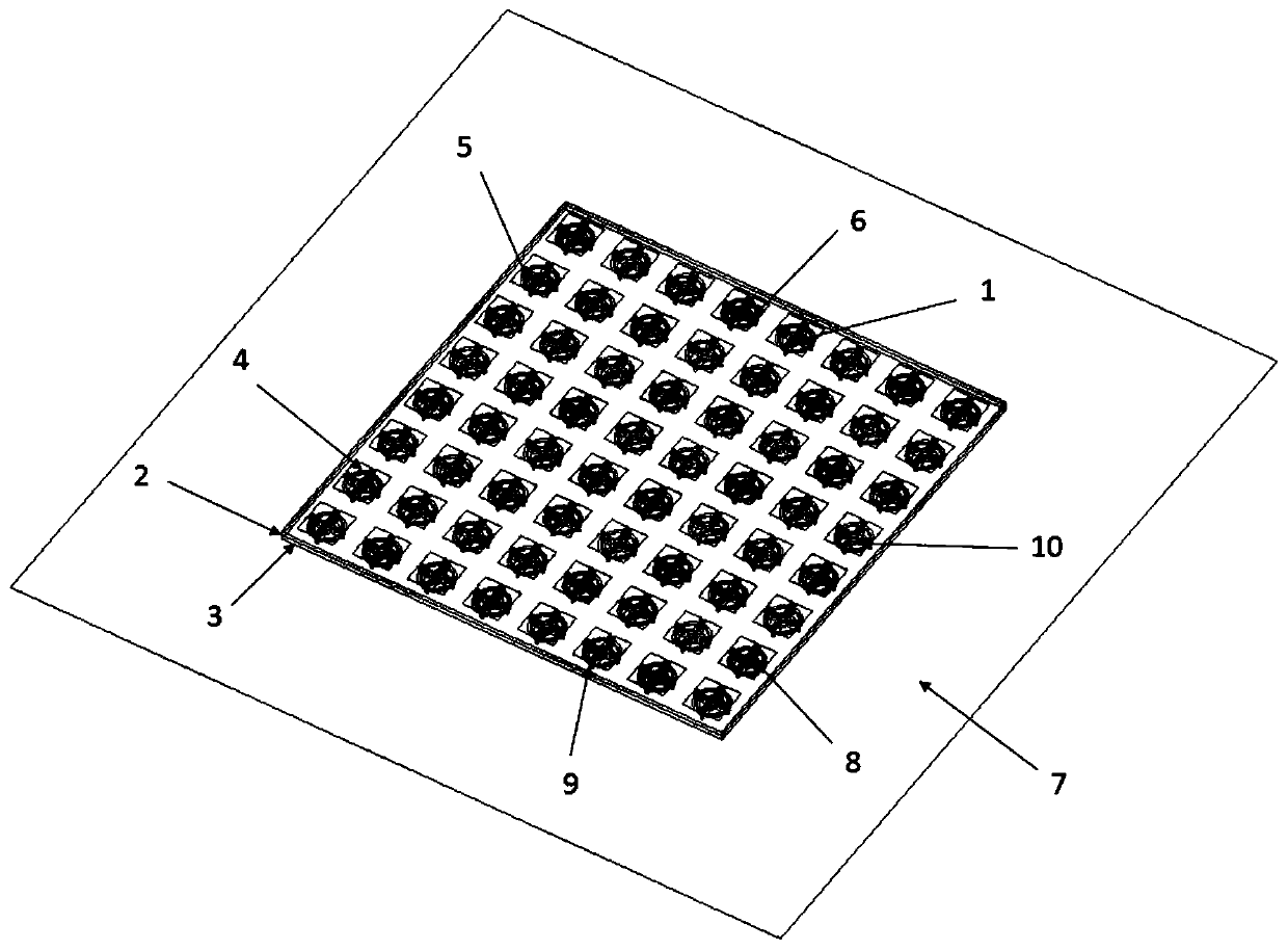
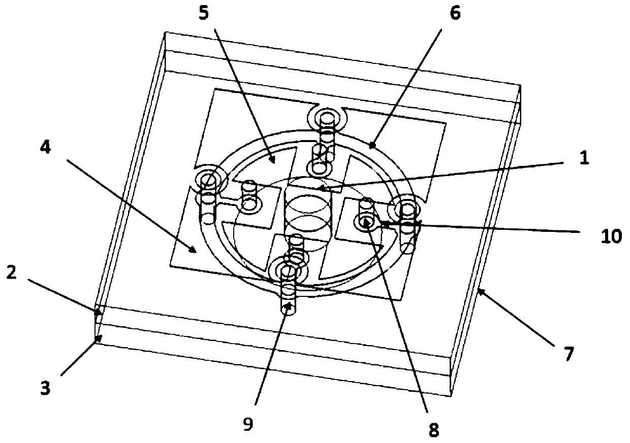
[0019] Please refer to figure 1 and figure 2 . figure 1 It is a three-dimensional structure diagram of a low-profile omni-directional scanning end-fire antenna array provided by an embodiment of the present invention. The antenna array shown in the figure is an 8×8 array, the array works in the X-band, the center frequency is 10GHz, and the array element spacing is λ 0 / 3, that is, 10mm; ...


PUM


Abstract

The invention discloses a low-profile omnidirectional scanning end-fire antenna array, which can realize omnidirectional scanning of the azimuth plane when the beam points to the end-fire direction. The relative bandwidth of the central unit of the array whose VSWR is less than 2 is greater than 20%, and the profile height is about 0.054λ 00 is the center frequency wavelength. The basic structure of the antenna unit includes: cylindrical feeding probe (1); upper dielectric substrate (2); lower dielectric substrate (3); top metal patch loading structure (4); middle inner metal patch loading structure ( 5); the middle outer ring metal patch loading structure (6); the floor (7); the metallized blind hole (8) connecting the top layer metal patch loading and the middle outer ring metal patch loading; connecting the middle outer layer The layer ring metal patch is loaded with the metallized through hole (9) of the subfloor; the middle layer metal line structure (10) connecting the metallized blind hole and the metallized through hole.

Description

technical field [0001] The invention belongs to the technical field of antenna engineering, and relates to a low-profile omnidirectional scanning end-fire antenna array. Low-profile end-fire antenna array with 360-degree scanning in azimuth direction. Background technique [0002] With the increasing application of wireless technology and the rapid development of military equipment technology, array antennas, as an important part of radar and communication systems, are increasingly used in different occasions. For array antennas used in special occasions, such as array antennas in airborne and missile-borne radars, on the one hand, the array antennas are required to have a small scanning blind area; Carrying capacity and maneuverability of the aircraft. Traditional radar and communication systems generally use side-firing antenna arrays, and the radiation direction of side-firing phased arrays is the normal direction of the array arrangement. The principle determines that ...

Claims


Application Information

Patent Timeline
Patent Type & Authority Patents(China)
IPC IPC(8): H01Q21/06H01Q1/38H01Q1/50H01Q1/48H01Q1/52
CPCH01Q1/38H01Q1/48H01Q1/50H01Q1/52H01Q21/061
Inventor 杨仕文王放陈益凯肖仕伟刘坤宁屈世伟
Owner UNIV OF ELECTRONICS SCI & TECH OF CHINA
Why Eureka
Try Eureka