Flow path switching valve

A flow path switching and valve chamber technology, applied in the field of flow path switching valves, can solve the problems of opening area changes, miniaturization difficulties, and complicated structures, etc., to reduce the driving torque, reduce the pressure difference, and reduce the load Effect

Active Publication Date: 2017-08-08
FUJIKOKI MFG CO LTD
View PDF7 Cites 2 Cited by
  • Summary
  • Abstract
  • Description
  • Claims
  • Application Information

AI Technical Summary

Problems solved by technology

Therefore, it is necessary to prepare pilot solenoid valves for driving the slide spool one by one when the flow path is switched, and there are problems such as complicated structure and difficulty in miniaturization.
In addition, in the case of using a solenoid valve as a pilot valve, there is a problem that the opening area of ​​the two ports changes rapidly at the time of switching, and the high-pressure refrigerant flows into the low-pressure side port (pipe) at one go. Rapid pressure changes in the cooling and heating system, resulting in loud noises (switching sounds)

Method used


Image

  • Flow path switching valve
  • Flow path switching valve
  • Flow path switching valve

Examples


no. 1 approach

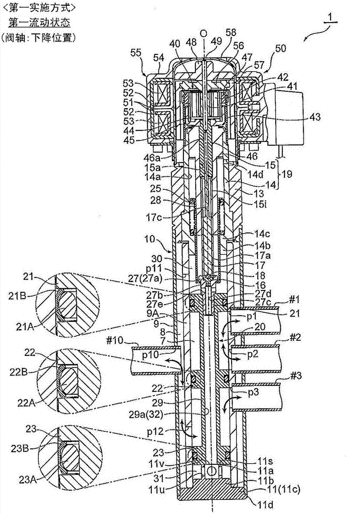
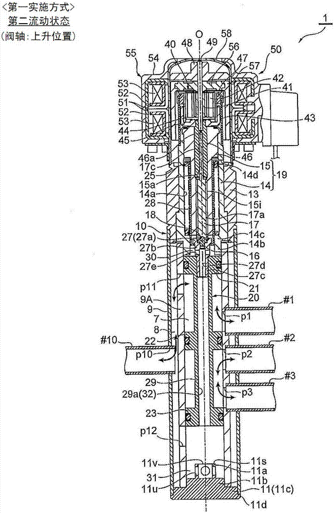
[0082] figure 1 and figure 2 It is a longitudinal sectional view showing the first embodiment of the channel switching valve of the present invention, figure 1 Indicates the first flow state (valve shaft: down position), figure 2 Indicates the second flow state (valve shaft: raised position).

[0083] In addition, in this specification, descriptions indicating positions and directions such as up and down, left and right, and front and rear are added for the convenience of the drawings to avoid cumbersome description, and are not limited to the positions and directions shown in the actual use state. direction.

[0084] In addition, in each figure, there are cases in which the gaps formed between components, the spacing distance between components, etc., are larger than the size of each component for easy understanding of the invention or for convenience in drawing. Or reduced to depict.

[0085] The flow path switching valve 1 of this embodiment is, for example, an elect...

no. 2 approach

[0113] Figure 4 as well as Figure 5 It is a longitudinal sectional view showing the second embodiment of the channel switching valve of the present invention, Figure 4 Indicates the first flow state (valve shaft: down position), Figure 5 Indicates the second flow state (valve shaft: raised position).

[0114] The channel switching valve 2 of the second embodiment differs from the channel switching valve 1 of the above-mentioned first embodiment basically only in the number of inner ports formed in the inner housing and the number of spools formed in the valve shaft. Therefore, components having the same functions as those in the first embodiment are denoted by the same symbols and their detailed descriptions are omitted, and only the above-mentioned differences will be described in detail below.

[0115] The flow path switching valve 2 of this embodiment is used as a six-way switching valve in, for example, a heat pump type refrigeration and heating system, etc., and th...

no. 3 approach

[0124] Figure 8 as well as Figure 9 It is a longitudinal sectional view showing the third embodiment of the channel switching valve of the present invention, Figure 8 Indicates the first flow state (valve shaft: down position), Figure 9 Indicates the second flow state (valve shaft: raised position).

[0125] Compared with the channel switching valve 2 of the above-mentioned second embodiment, the channel switching valve 3 of the third embodiment is basically different in the opening position of the outer port and the shape of the communication space between the outer case and the inner case. different. Therefore, components having the same functions as those in the second embodiment are denoted by the same symbols and their detailed descriptions are omitted, and only the above-mentioned differences will be described in detail below.

[0126] The channel switching valve 3 of the present embodiment is used as a six-way switching valve in, for example, a heat pump cooling...


PUM


Abstract

Provided is a flow path switching valve which can efficiently switch fluid flow direction (flow path) with a relatively simple constitution and contribute to further miniaturization, large capacity, power saving, etc. At least two inner ports (p1 to p3) opening into a valve chamber (7) are opened in an inner housing (9A) so as to be spaced apart from each other in the direction of the axis O, and at least one communcaiton port (p11 to p12) communicating with the valve chamber (7) and the communicating space (8) at all times. One of the communication ports (p11 and p12) is opened and an outer port (p10) which always communicates with the communication space (8) is opened in the outer housing (9) so that the upper back pressure chamber (30) and the lower back pressure chamber (31) are always in communication The valve shaft (20) is raised and lowered in the valve chamber (7) in a state where at least two valve bodies (21 to 23) provided on the valve shaft (20) are in contact with the inner housing (9A), whereby at least two inner ports (p1-p3) and the outside port (p10) are switched.

Description

technical field [0001] The present invention relates to a flow path switching valve, and relates to a flow path switching valve used, for example, in an electric valve of a heat pump refrigeration and heating system. Background technique [0002] Conventionally, as this kind of flow path switching valve, a structure as follows is known (for example, refer to the following patent document 1), by using a pilot solenoid valve using an electromagnetic coil, the sliding valve element is used to switch the refrigerant flow path. The valve body of the six-way valve or eight-way valve moves inside the valve body to switch the communication state of the port provided on the valve seat, that is, the flow direction (flow path) of the refrigerant, and perform cooling operation (defrosting operation) and heating Operation switching. [0003] prior art literature [0004] patent documents [0005] Patent Document 1: Japanese Patent Application Laid-Open No. 8-170864 [0006] The probl...

Claims


Application Information

Patent Timeline
Patent Type & Authority Applications(China)
IPC IPC(8): F16K11/07F16K27/04F16K31/04F16K3/314F25B41/06
CPCF16K3/314F16K11/07F16K27/041F16K31/046F25B41/30
Inventor 原田贵雄柳泽秀小泉佑树
Owner FUJIKOKI MFG CO LTD
Why Eureka
Try Eureka