Sintering flue gas autocatalysis-based flue gas circulating denitrification system

A technology of flue gas circulation and sintering flue gas, which is applied in the field of flue gas circulation and denitrification system, can solve the problems of waste heat of sintering flue gas, large investment in flue gas denitrification, high waste heat recovery rate, etc., achieves reduction of NOx emissions and broad market application The effect of the foreground, smoke and dust with a large amount of dust

Active Publication Date: 2017-08-11
武汉钢铁有限公司 +2
View PDF11 Cites 5 Cited by
  • Summary
  • Abstract
  • Description
  • Claims
  • Application Information

AI Technical Summary

Problems solved by technology

[0015] The purpose of the present invention is to solve the above-mentioned technical problems, aiming at the waste of waste heat of sintering flue gas in the existing sintering system, large investment and high cost of flue gas denitration, etc., to provide a simple system, no externally purchased denitrification catalyst, self-catalyzed denitrification by sintering dust, Flue gas circulation denitrification system based on sintering flue gas autocatalysis with high waste heat recovery rate, small footprint, environmental friendliness, low investment in denitrification equipment and low denitrification operation cost

Method used


Image

  • Sintering flue gas autocatalysis-based flue gas circulating denitrification system
  • Sintering flue gas autocatalysis-based flue gas circulating denitrification system

Examples


Embodiment Construction

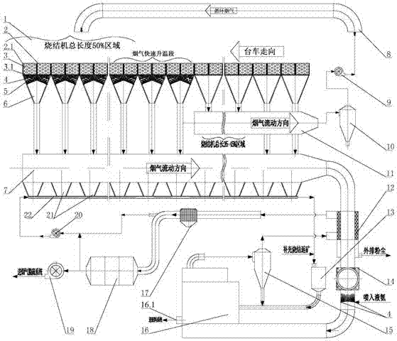
[0043] see figure 2 , including a sintering machine 2, a bellows 6 is provided under the trolley 2.1 of the sintering machine 2, and the outlet at the bottom of the bellows 6 is connected to the flue gas pipeline, and the sintering machine 2 is sequentially divided into an ignition section, a head section, a smoke Gas rapid heating section and tail section 4 areas, the flue gas pipeline is composed of main flue 7 and circulating flue gas main flue 11, the tail section, flue gas rapid heating section and ignition section of the sintering machine 2 The air box 6 below the area is connected to the main flue 7, and the bellows 6 below the nose section area is connected to the main flue 11 of circulating flue gas; wherein, the bottom of the main flue 7 is provided with a main flue powder hopper 21, and the main flue powder The bottom of the hopper 21 is connected to a dust pneumatic conveying pipe 22 , and the outlet of the dust pneumatic conveying pipe 22 is connected to the flui...


PUM


Abstract

The invention relates to a sintering flue gas autocatalysis-based flue gas circulating denitrification system. According to the technical scheme, the system comprises a sintering machine, wherein an air box is arranged at the lower part of a trolley of the sintering machine; an outlet in the bottom of the air box communicates with a flue gas pipe; the sintering machine is sequentially divided into four areas, namely an ignition segment, a machine head segment, a flue gas quick heating segment and a machine tail segment along an advancing direction of the trolley; the outlet of a main flue powder hopper at the lower part of the flue gas pipe connected with the air box in the areas of the machine tail segment and the flue gas quick heating segment is connected with a dust pneumatic conveying pipe; and the outlet of the dust pneumatic conveying pipe is connected to a fluidized bed denitrification reactor through a particle material cabin. The system provided by the invention is simple, high in afterheat recovery rate, small in floor area, friendly to environment, economical in denitrification equipment investment and low in denitrification operation cost, and autocatalytic smoke denitrification is carried out without purchasing a denitrification catalyst.

Description

technical field [0001] The invention relates to a flue gas denitrification system in the field of environmental protection, in particular to a flue gas circulation denitrification system based on sintering flue gas autocatalysis. Background technique [0002] Generally speaking, the waste heat of the main flue gas of the sintering machine accounts for 13-23% of the energy consumption of the sintering process, and the waste heat of the exhaust gas of the cooler (ring cooler or belt cooler) accounts for 19-35% of the energy consumption of the sintering process. And up to 50-60%. At present, many enterprises have recycled the waste heat of the exhaust gas of the cooling machine, but few enterprises have recycled the waste heat of the main flue gas of the sintering machine. [0003] Sintering flue gas circulation is one of the effective schemes for waste heat recovery and utilization of sintering flue gas. The basic process route is to reintroduce part of the sintering heat was...

Claims


Application Information

Patent Timeline
Patent Type & Authority Applications(China)
IPC IPC(8): B01D53/90B01D53/56F27D17/00
CPCB01D53/8628B01D53/8631B01D53/90B01D2251/2062B01D2255/20738B01D2258/0283F27D17/004F27D2017/005
Inventor 吴高明姚茜卫书杰吴晓辉
Owner 武汉钢铁有限公司
Why Eureka
Try Eureka