Mechanical arm driven in compound manner

A robotic arm and composite technology, applied in the direction of manipulators, program-controlled manipulators, claw arms, etc., can solve the problems of potential safety hazards, large space occupation, and production space occupation, so as to increase the stroke range, improve production efficiency, and improve operation accuracy. Effect

Pending Publication Date: 2017-08-11
柳州科瑞科技有限公司 +1
View PDF10 Cites 5 Cited by
  • Summary
  • Abstract
  • Description
  • Claims
  • Application Information

AI Technical Summary

Problems solved by technology

[0003] However, the stroke of this kind of mechanical arm on the Z axis is greatly affected by the height of the arm profile. When a large vertical stroke is required, it must be realized by increasing the height of the arm profile, thereby occupying more production space; too long The arm profile also reduces the accuracy of the operation, affecting the overall quality and efficiency of the automated production line
[0004] The utility model patent with the patent announcement number CN204109003U discloses a double telescopic mechanical arm. The patent uses a single motor to drive the nut, and the nut drives the screw fixed to the No. 1 mechanical arm. The No. 1 mechanical The Z-direction movement of the arm is driven by only one motor, and its load often cannot meet the production of relatively large-mass parts. Once the quality of the material exceeds its load-bearing range, it will have a serious impact on the reliability and stability of the machine. , often lead to production accidents; and the patent adopts double guide wheels and double belts, which relatively takes up a lot of space. The fixed seat with the guide wheels is directly installed on the upper part of the No. 1 mechanical arm, and the guide wheels are almost completely exposed. Outside, there are also security risks

Method used


Image

  • Mechanical arm driven in compound manner
  • Mechanical arm driven in compound manner
  • Mechanical arm driven in compound manner

Examples


Embodiment Construction

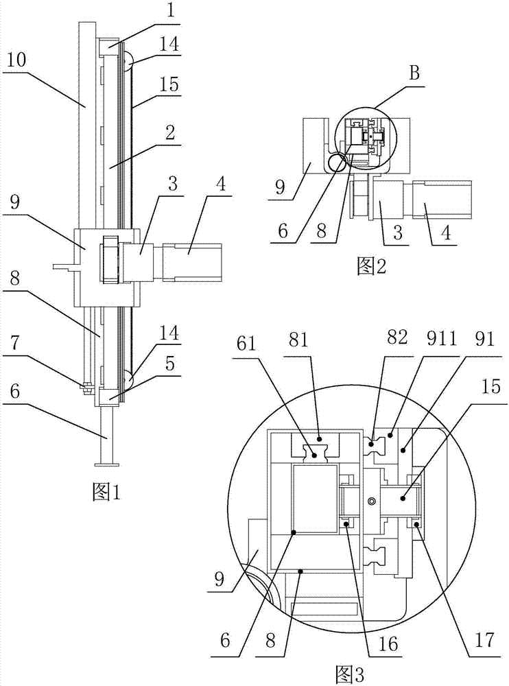
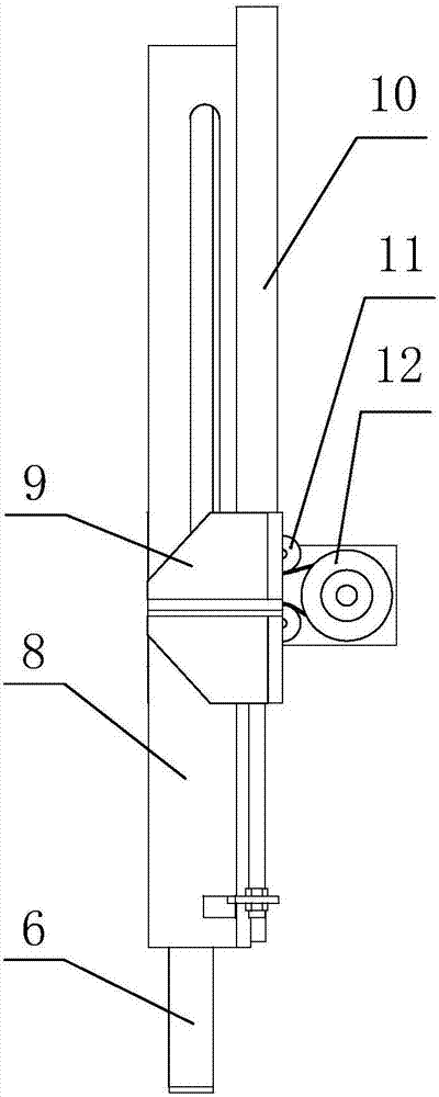
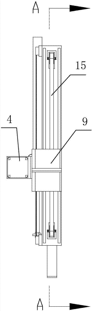
[0028] A mechanical arm with compound transmission, including a double sliding arm and a driving device, the double sliding arm includes an outer sliding arm and an inner sliding arm nested in the outer sliding arm and slidingly connected with the outer sliding arm, the outer sliding arm includes Outer profile 8, the outer profile is a rectangular long frame tube, the inner side of the outer profile is provided with a slide block 81, the outer side of the outer profile is provided with a slide rail 82, and the outer profile is fixed on the machine base through the slide rail 82 on the outer side The slide rail seat 9 on the body is slidably connected, the inner slide arm includes the inner profile 6, and the outer surface of the inner profile is provided with a slide rail 61, and the inner profile slides and cooperates with the outer profile through the slide rail on the outer surface and the slider on the inner surface of the outer profile ;

[0029] The driving device is a d...


PUM


Abstract

A mechanical arm driven in a compound manner comprises double slide arms and drive devices. The double slide arms include the outer slide arm and the inner slide arm embedded in the outer slide arm and connected with the outer slide arm in a sliding manner. The outer slide arm is connected with a slide rail base through slide rails in a sliding manner. The drive devices are installed on the slide rail base and include the first drive device and the second drive device. The first drive device comprises a servo motor, a speed reducer and a belt wheel I. The servo motor drives a conveyor belt I through the speed reducer and the belt wheel I so that an outer profile can be driven to slide up and down. The second drive device comprises a cylinder. A piston rod of the cylinder is connected with the outer profile and pushes the outer profile to slide. Two belt wheels II are arranged on the outer profile. A conveyor belt II is assembled between the belt wheels II. The inner side of the conveyor belt II is fixed to an inner profile, and the outer side of the conveyor belt II is fixed to the slide rail base. The outer profile moves up and down so as to drive the inner profile to move up and down at a double speed relative to the outer profile. By means of the mechanical arm, the stroke is increased, space is saved, the operation precision and efficiency are improved, the material mass range is widened, and safety is high.

Description

technical field [0001] The invention relates to a mechanical arm, in particular to a compound transmission mechanical arm. Background technique [0002] Traditional industrial robots are used in actual automated production in consideration of production safety and process requirements. It is often necessary to increase the up and down stroke (Z axis), while the traditional method is to simply increase the length of the mechanical arm. The mechanical arm is fixed on the slide rail. The cylinder assembly or servo motor assembly on the seat drives the arm profile, so that the fixed slide rail on the arm profile slides relative to the slider on the slide rail seat, so as to realize the purpose of moving the arm in the Z-axis direction. [0003] However, the stroke of this kind of mechanical arm on the Z axis is greatly affected by the height of the arm profile. When a large vertical stroke is required, it must be realized by increasing the height of the arm profile, thereby occu...

Claims


Application Information

Patent Timeline
Patent Type & Authority Applications(China)
IPC IPC(8): B25J9/12B25J9/14B25J18/00
CPCB25J9/12B25J9/14B25J18/00
Inventor 李健苏海迪刘邦雄吴量梁鹏
Owner 柳州科瑞科技有限公司
Why Eureka
Try Eureka