Gearbox lubricating and cooling system and gearbox

A lubricating cooling and transmission technology, applied in gear lubrication/cooling, transmission parts, belts/chains/gears, etc., can solve problems such as limitation, difficulty in clutch separation and combination control, complex oil circuit and hardware structure, etc. To achieve the effect of life-enhancing

Active Publication Date: 2017-08-11
捷孚传动科技有限公司
View PDF15 Cites 3 Cited by
  • Summary
  • Abstract
  • Description
  • Claims
  • Application Information

AI Technical Summary

Problems solved by technology

[0003] In terms of cooling and lubrication of gearbox gears, some of the current dual-clutch gearboxes still use traditional splash lubrication. Due to the layout of the gear transmission system, limited by the principle of splash lubrication, the design and performance of the gear shaft have been raised. Huge challenge; some also use forced lubrication, but the oil circuit and hardware structure are very complicated, which puts forward higher requirements for the design and production process of parts, such as Chinese patents CN203516692U, CN104196991B
Chinese patent CN106321805A discloses a lubricating and cooling oil circuit, but the lubricating and cooling oil circuit only provides cooling and lubrication for the clutch, and the flow and pressure of the cooling lubricating oil are not controlled by the spool, and the flow of the lubricating and cooling oil is uncontrollable, resulting in the entire Inefficient lubrication cooling system
If the clutch lubricating pressure is too high, it will cause difficulty in controlling the separation and coupling of the clutch. When the pressure of the clutch control circuit is relatively low, the clutch cannot be combined due to the high lubricating pressure.

Method used


Image

  • Gearbox lubricating and cooling system and gearbox

Examples


Embodiment Construction

[0026] The present invention will be described in detail below with reference to the specific embodiments shown in the accompanying drawings. However, these embodiments are not limited to the present invention, and structural, method, or functional transformations made by those of ordinary skill in the art based on these embodiments are all included in the protection scope of the present invention.

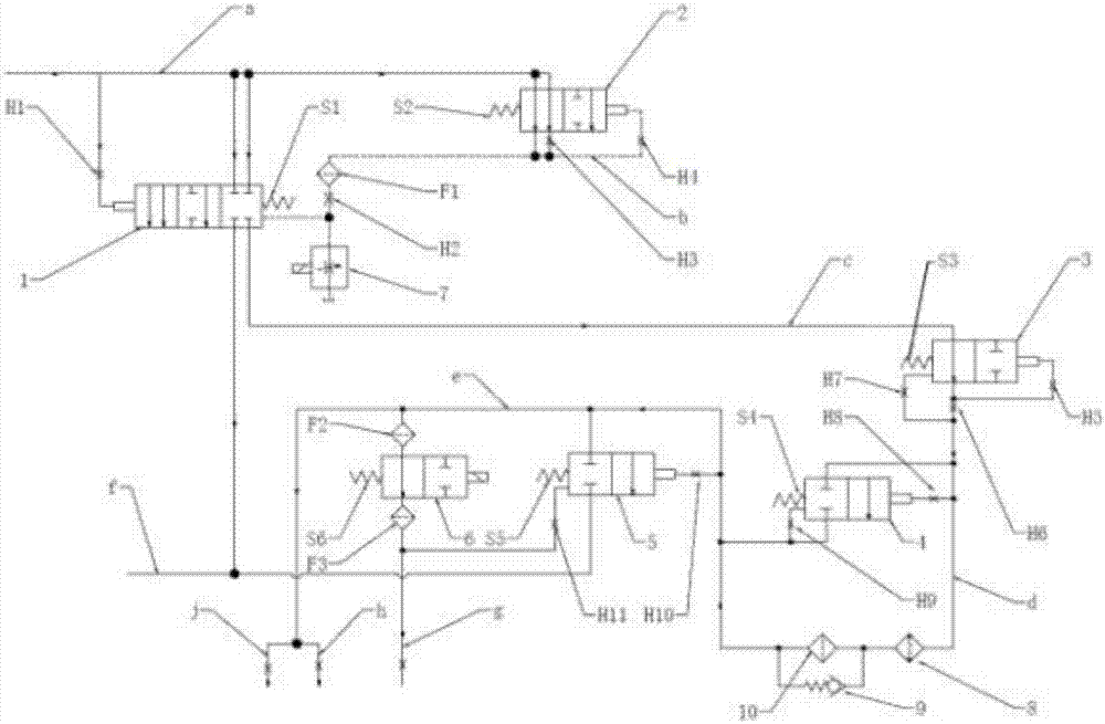
[0027] like figure 1 As shown, the present invention discloses a transmission lubrication and cooling system, and the direction of the arrow in the figure represents the flow direction of hydraulic oil. The transmission lubrication cooling system includes an oil tank for supplying hydraulic oil, a main oil pressure control valve 1 for controlling main oil pressure, and a main oil circuit a for outputting hydraulic oil from the oil tank and a main oil pressure control valve 1 for outputting hydraulic oil from the oil tank. The lubricating oil circuit c output from the control valv...


PUM


Abstract

The invention discloses a gearbox lubricating and cooling system. The gearbox lubricating and cooling system comprises an oil tank, a main oil circuit, a main oil pressure control valve and a lubricating oil circuit. A lubricating and cooling oil circuit is divided into two oil circuit bodies which are used for clutch lubricating and gearbox inner bearing lubricating correspondingly. The output end of a lubricating flow control valve is connected with a residual stress control valve through an oil circuit. The lubricating and cooling oil circuit further communicates with an oil drainage oil circuit through the residual stress control valve. The output end of the oil drainage oil circuit leads to the oil tank. The output end of the lubricating flow control valve communicates with the spring end of the residual stress control valve. The gearbox lubricating and cooling system mainly has the beneficial effects that the effect that the lubricating and cooling system has stable pressure and flow is ensured through self feedback of the flow control valve and the dynamic balance between hydraulic oil and a spring; and the residual stress control valve is arranged, so that the maximum oil pressure of the lubricating and cooling system is limited, and the safety of the lubricating and cooling system is ensured.

Description

technical field [0001] The invention relates to a lubricating and cooling device for a double clutch of a gearbox and a bearing, in particular to the lubrication of a wet double clutch and a bearing, in particular to a lubricating system for a gearbox. Background technique [0002] The function of the transmission lubrication system is to provide lubricating oil to the rolling or sliding parts of the dual clutches and bearings inside the transmission to ensure fluid lubrication of the friction surfaces, reduce friction and wear, and cool the lubricated parts at the same time. With the development of society and the advancement of science and technology, people's requirements for driving comfort and fuel economy are getting higher and higher, and the requirements for emission standards are more stringent, which promotes the rapid development of dual-clutch transmission technology. The dual-clutch gearbox has a unique structure and working principle, its working conditions are...

Claims


Application Information

Patent Timeline
Patent Type & Authority Applications(China)
IPC IPC(8): F16H57/04
CPCF16H57/0412F16H57/0434F16H57/0442F16H57/0471
Inventor 朱顺利任旻薛翔王治华
Owner 捷孚传动科技有限公司
Why Eureka
Try Eureka