Energy-conservation eco-friendly intelligent monitoring device for indoor environment
An energy-saving, environmental protection, and environmental monitoring technology, applied in the field of communication, can solve problems such as long measurement time, imperfect functions, and difficult work, and achieve the effects of increasing utilization, improving air quality, and facilitating monitoring
- Summary
- Abstract
- Description
- Claims
- Application Information
AI Technical Summary
Problems solved by technology
Method used
Image

Examples
Embodiment 1
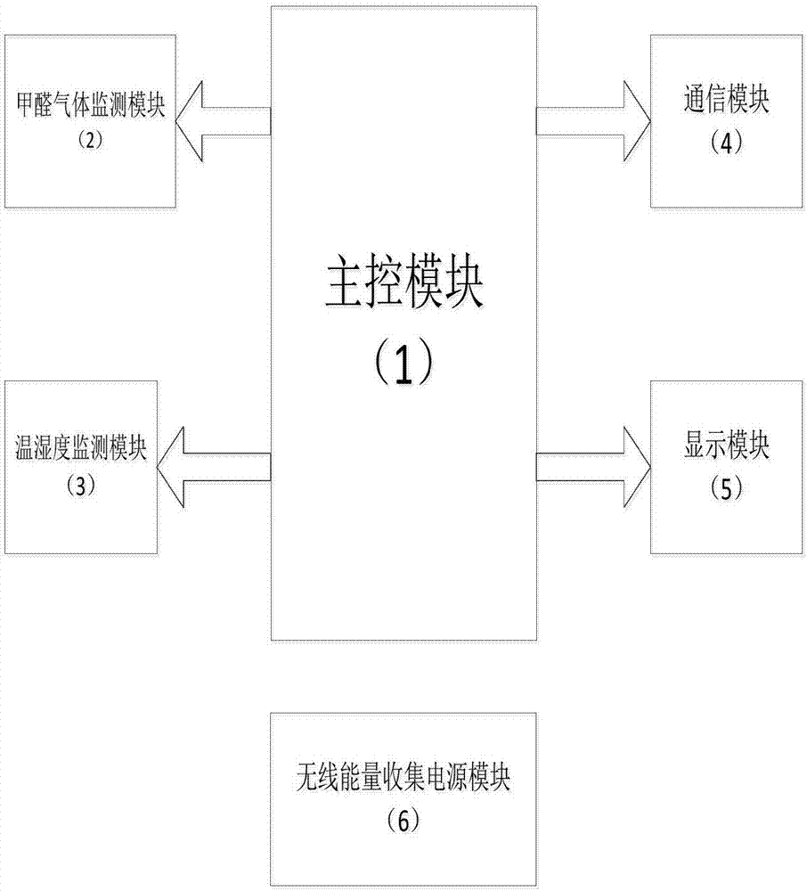
[0036] Embodiment 1 Overall structure of the present invention
[0037] refer to figure 1 , the present invention is an energy-saving and environment-friendly intelligent indoor environment monitoring device, which has a main control module 1, a formaldehyde gas monitoring module 2, a temperature and humidity monitoring module 3, a communication module 4, a display module 5 and a wireless energy harvesting power supply module 6 . The formaldehyde gas monitoring module 2 , the temperature and humidity monitoring module 3 , the communication module 4 and the display module 5 are all connected to the main control module 1 . The main control module 1 is responsible for coordinating the work among the modules. The formaldehyde gas monitoring module 2 detects the concentration of formaldehyde gas in the current indoor air and sends the corresponding data to the main control module 1. At the same time, when the formaldehyde gas in the indoor air exceeds the standard 4 Send alarm in...
Embodiment 2
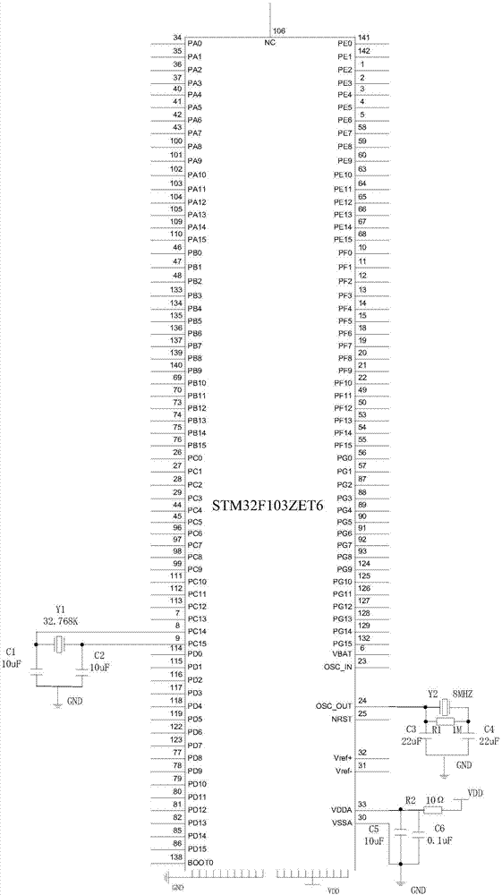
[0038] Embodiment 2 Main control module 1 of the present invention
[0039] refer to figure 2 , the structure of the main control module 1 of the present invention is: ARM chip STM32F103ZET6 pin 8 and pin 9 are connected to a crystal oscillator Y1 with a frequency of 32.768KHz. One end of the crystal oscillator Y2 with a frequency of 8MHz, the two ends of the crystal oscillator Y2 are respectively connected to the two ends of the resistor R1, and are also grounded through the capacitors C3 and C4 respectively, the 30 pin of the STM32F103ZET6 is grounded, the 33 pin is connected to the power supply VDD through the resistor R2, and the 33 pin Also ground through two parallel capacitors C5 and C6, 16 pins, 38 pins, 51 pins, 61 pins, 71 pins, 83 pins, 94 pins, 107 pins, 120 pins, 130 pins and 143 pins are grounded, 17 pins, 39 pins Pins, 52 pins, 62 pins, 72 pins, 84 pins, 95 pins, 108 pins, 121 pins, 131 pins and 144 pins are all connected to the power supply VDD.
Embodiment 3
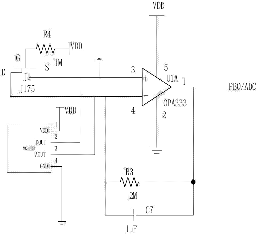
[0040] Embodiment 3 Formaldehyde gas monitoring module 2 of the present invention
[0041] refer to image 3 , the structure of the formaldehyde gas monitoring module 2 of the present invention is: 1 pin of the MQ-138 sensor is connected to the power supply VDD, 4 pins are grounded, 2 pins and 3 pins are respectively connected to the non-inverting input end and the inverting input end of the operational amplifier U1A, and the operational amplifier Pin 4 of U1A is connected to one end of resistor R3, one end of capacitor C7 and the drain of FET J1 at the same time, the other end of resistor R3 and capacitor C7 is connected to pin 1 of operational amplifier U1A, and pin 2 of operational amplifier U1A is grounded, 5 The pin is connected to the power supply VDD, the pin 3 is connected to the source of the field effect transistor J1 and grounded, the gate of the field effect transistor J1 is connected to one end of the resistor R4, the other end of the resistor R4 is connected to t...
PUM
 Abstract
Description
Claims
Application Information