
Air-cooled permanent-magnet coupler and method for cooling the same

A permanent magnet coupler, air-cooled technology, applied in the direction of permanent magnet clutch/brake, electric brake/clutch, cooling/ventilation device, etc. Advanced problems, to ensure reliable operation, improve efficiency and degree of effect

Pending Publication Date: 2017-08-11
北京必可测科技股份有限公司
View PDF7 Cites 3 Cited by
  • Summary
  • Abstract
  • Description
  • Claims
  • Application Information

AI Technical Summary

Problems solved by technology

[0005] At present, different types of permanent magnetic couplers adopt different cooling methods. The air-cooled permanent magnetic coupler has a simple structure, and the main heat dissipation depends on the installation of aluminum heat dissipation fins on the outside of the guide disk, and relies on the rotational speed to form eddy currents. The heat is brought out, and the purpose of heat exchange and cooling can be achieved by forming a temperature difference in the surrounding air, so that the permanent magnetic coupler can operate reliably; the structure of the water-cooled permanent magnetic coupler is relatively complicated, and there are certain requirements for water quality. The waterway design involved It is complex and requires circulation system, cooling system, external water cooling system control system and feedback system, etc. There are many fault points, and it is necessary to increase the pipes and nozzles and use water as the cooling medium to take away the heat from the guide disk so that the permanent magnetic coupler can operate reliably. ; The structure of the oil-cooled permanent magnetic coupler is complex, and the oil occupies a large area, including the cooling system and the feedback system, etc., and the oil quality needs to be measured, and the environment is poor. and reuse the hot oil after cooling to achieve reliable operation of the permanent magnetic coupling
[0006] It can be seen that for high-power permanent magnet couplers, that is, water-cooled permanent magnet couplers or oil-cooled permanent magnet couplers with power above 400kw, the cooling is complicated and the efficiency and degree of cooling are not high, which will affect the performance of water-cooled permanent magnets. Reliable operation of couplings or oil-cooled permanent magnetic couplings

Method used


Image

  • Air-cooled permanent-magnet coupler and method for cooling the same
  • Air-cooled permanent-magnet coupler and method for cooling the same
  • Air-cooled permanent-magnet coupler and method for cooling the same

Examples


Embodiment Construction

[0048] In order to make the object, technical solution and advantages of the present invention clearer, the present invention will be further described in detail below with reference to the accompanying drawings and examples.

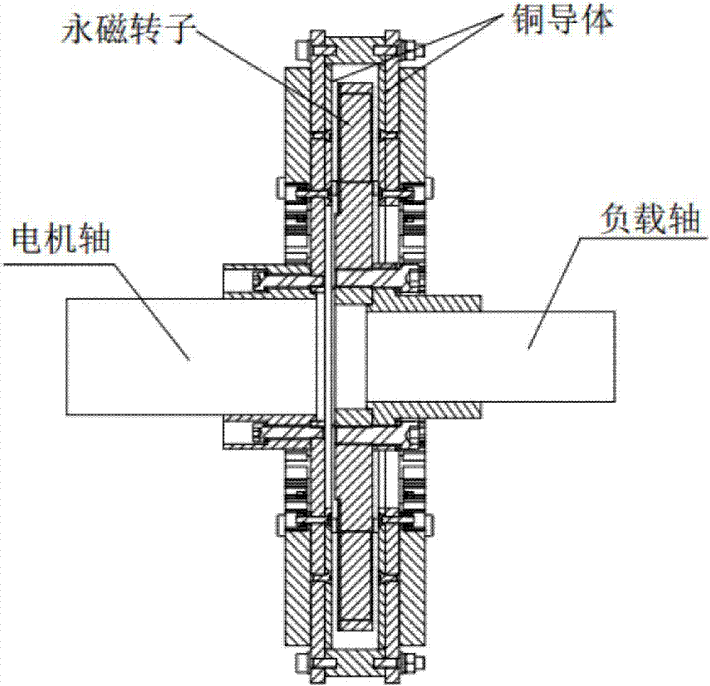
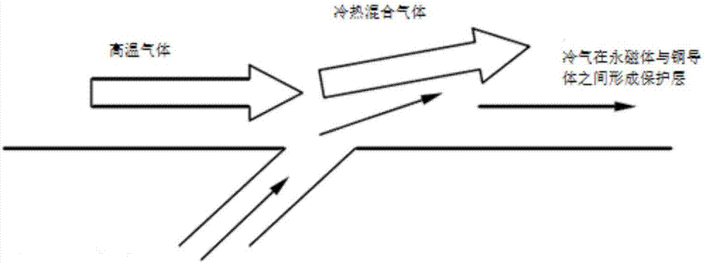
[0049] In order to improve the efficiency and degree of cooling and ensure the reliable operation of the permanent magnetic coupler, especially for the high-power permanent magnetic coupler, the embodiment of the present invention adopts the air film technology, and the copper conductor and the copper conductor in the air-cooled permanent magnetic coupler An insulating air film is formed between the permanent magnet rotors to cool the copper conductors and the permanent magnet rotors while insulating the heat transfer between the copper conductors and the permanent magnet rotors.

[0050] Since the air-cooled permanent magnetic coupler using this air film technology can greatly reduce the operating temperature, its working power can be increased, such as...


PUM


Abstract

The invention discloses an air-cooled permanent-magnet coupler and a method for cooling the same. On the basis of the gas film technique, an isolation gas film is formed between a copper conductor and a permanent-magnet rotor in an air-cooled permanent-magnet coupler. Therefore, while the copper conductor and the permanent-magnet rotor are cooled, heat transferring between the copper conductor and the permanent-magnet rotor is isolated, so that the cooling efficiency and degree are increased and thus reliable operation of the permanent-magnet coupler can be guaranteed.

Description

technical field [0001] The invention relates to permanent magnet drive technology in the industrial field, in particular to an air-cooled permanent magnet coupler and a method for cooling the air-cooled permanent magnet coupler. Background technique [0002] Permanent magnet drive technology is a breakthrough new technology developed internationally in recent years. It is an applicable technology for speed regulation and energy saving of fans and pump centrifugal loads. It has the characteristics of high efficiency and energy saving, high reliability, no rigid connection to transmit torque, can be applied in harsh environments, greatly reduces the overall system vibration, reduces system maintenance and prolongs the service life of the system. In particular, its excellent speed regulation characteristics of no high-order harmonics and no heating of the motor at low speeds make it the first choice for energy-saving technical transformation of fans and pumps. [0003] The per...

Claims


Application Information

Patent Timeline
IPC IPC(8): H02K49/10H02K9/02H02K5/18
CPCH02K5/18H02K9/02H02K49/108H02K2205/09Y02T10/64
Inventor 黄俊飞
Owner 北京必可测科技股份有限公司
Learn More